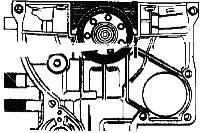
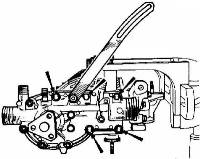
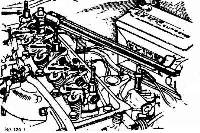
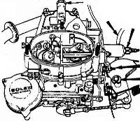
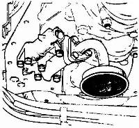
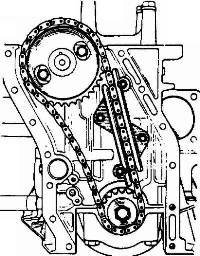
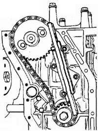
The cutaway view of the engine/gearbox (transmission) unit shown on the opposite page provides an indication of the grouping of the components and in which section of the manual they may be found.
Description of component Section. AIR CLEANER .......................................................... L (FUEL SYSTEM} CARBURETTOR .......................................................... L (FUEL SYSTEM) FUEL PUMP ............................................................ L (FUEL SYSTEM) DISTRIBUTOR .......................................................... M (ELECTRICAL EQUIPMENT') SPARKING PLUGS ....................................................... M (ELECTRICAL EQUIPMENT) CLUTCH ............................................................... Q (CLUTCH) WATER PUMP............................................................ E (ENGINE) CRANKSHAFT ........................................................... E (ENGINE) SUMP, CRANKCASE ...................................................... E (ENGINE) CAMSHAFT, VALVE GEAR ................................................. E (ENGINE) GEARBOX .............................................................. F (TRANSMISSION) DRIVE SHAFTS ......................................................... F (TRANSMISSION) |
E.1. MODEL IDENTIFICATION - Section Menu
The type, index and manufacturing number are given on a number plate, which is riveted to the left-hand side of the engine.
E.2 CROSS SECTIONS - Section Menu
E.3 - REMOVING AND REFITTING THE ENGINE - Section Menu
The engine cannot be removed as an individual unit and consequently must be removed together with the transmission as one assembly.
A - REMOVING THE ENGINE
Before commencing operations, place protective coverings on body sides around the engine compartment. Remove the engine compartment lid carefully by detaching the component at its hinge mountings (two nuts and penny washers per hinge).
-
Remove the rear luggage compartment by undoing the two bolts set in the floor of the unit, taking care to note the quantity and position of spacer washers situated between the cross member and the undersurface of the compartment.
Disconnect the battery cables (earth first).
Drain the cooling system (see section K). Drain the transmission using drain plug wrench 46F 6167 (see section F).
Drain the petrol tank (see section L).
Remove the air filter from the (see section L).

Disconnect and remove the header tank, by undoing the pipe clips and the nut securing the leg of the tank to the chassis.
The vent pipe to the filler neck can be simply pulled through the aperture in the side of the engine compartment.

Disconnect the water return hose.
Disconnect the brake servo vacuum hose.

Disconnect the alternator leads and remove the unit.
Disconnect the inlet pipe at the fuel pump.
Disconnect the fuel pipe at the "T-piece" adjacent to the pump.
Disconnect the input lead at the ignition coil.
Disconnect the heater radiator hoses at the water pump and heater control valve.
Disconnect the heater control valve wire.
Disconnect the lead from the temperature sender.
Disconnect the starter leads.

Disconnect at the: the accelerator cable, the solenoid valve, the choke wire.
Remove the upper bolt on the starter mounting flange.
Disconnect the speedometer drive cable at the gearbox.
Disconnect the leads to the reversing light switch and remove the switch.
Remove the bolt, which secures the reaction rod to the bracket on the top of the gearbox.
Replace the bolt and the spacers on the rod for safe keeping.
Series one vehicles only:

Remove the vertical bolt holding the gear change bell-crank to the bracket on the engine timing case.

Remove the bolt (or circlip-series one cars), which secures the rear gear control shaft to the cross shaft lever at the rearmost rose joint.
Remove the hub caps from the two rear road wheels.
Slightly slacken the nuts of the rear road wheels.
Chock the front road wheels.

Raise the rear of the car and support the vehicle by placing stands beneath the chassis at the positions indicated.
Remove the rear road wheels.

Remove the two top suspension unit mounting bolts, allowing the spring/damper units to take up their fully extended condition,
Unscrew the four bolts retaining the rear chassis cross member to the chassis and remove the member.
Dismantle the exhaust system by:
-
a) Removing the tail pipe and silencer (muffler) assembly.
-
Undo the nut attaching the silencer strap to the clutch housing.
Remove the two bolts securing the silencer bracket to the gearbox.
Undo the clip clamping the silencer to the front pipe and withdraw the component rearwards.
-
Undo the two nuts securing the clamp ring and release the pipe from the manifold.

Drive the pins from the inner universal joints on the transmission shafts by means of a drift
(Part No 46F 6171).
With the chassis cross member and exhaust system removed, it is possible to stand within the confines of the engine compartment, thus simplifying this operation.
Care must be exercised that the drift be struck 'solidly and squarely' as light 'tapping attempts' may only succeed in burring the components.
Free the transmission shafts from the sun wheel by withdrawing them outwards from their splines.
Note that shims are used on the shafts and must be replaced on reassembly.

Disconnect the clutch cable from the lever at the clutch housing.
Remove the clutch outer cable from the right hand engine mounting by withdrawing it forwards.
Remove the bolt, which secures the earth (ground) lead to the cylinder block.
Disconnect the wire to the oil light switch.
Disconnect the wire to the oil pressure sender unit.

Unscrew the two nuts, which secure the gearbox insulator to the chassis. Note position of the washers.
Position a hoist above the unit and attach the sling (Part No 46E 6431).

Secure the sling at the upper mounting bolt hole of the starter motor on the left hand side of the engine.

Secure the right hand leg of the sling at the point where the earth (ground) lead is normally attached to the cylinder block.
The hook lug of the sling will rest against the alternator support on the distributor side.
IMPORTANT: IT IS FORBIDDEN TO USE ANY FORM OF LIFTING EQUIPMENT WHICH TAKES THE LOAD UNDER THE MANIFOLD OR WHICH IS RETAINED BY THE CYLINDER HEAD BOLTS. USE ONLY SLING (Part No 46E 6431).

Take the weight of the engine/gearbox unit by means of the hoist and remove the four bolts, which secure the engine mounting plates to the insulators.
Slowly raise the engine/gearbox unit clear of its chassis locations.

Remove the three bolts securing the right hand engine mounting plate to the cylinder block. Slide the engine mount rearwards along the rear gear shaft to facilitate the removal of the engine/gearbox unit. To simplify the removal of the three bolts the oil filter may be removed using tool (Part No 46E 6432).
Care must be exercised to avoid damaging the edges of the engine compartment aperture as the unit is swung out.

Place the unit on stand (Part No 46E 6365).
Remove the lifting shackle, the starter, the outer flange from the camshaft pulley, the pulley adjusting shims, the belt, the pulley.
Unlock and remove the three clutch housing securing bolts on the engine.
Separate the gearbox from the engine.
B - REFITTING THE ENGINE - Section Menu
-
Carry out the removing operations in reverse paying attention to the following points:
-
Lightly grease the clutch shaft splines.
Grease the gearbox output shaft splines.
Align the pin hole in one of the splines in the transmission shaft with that on the top of one of the splines of the output shaft.

To make fitting the transmission shaft pins easier, use the cranked end of drift (Part No 46F 6171).
Check adjustment of gear change reaction rod (see section F).

Check that the leakage hole in the thermostat is towards the top and in line with the slot in the water pump body.
Tighten the hose clips using special key (part No 46E 6433).
When re-fitting the distributor, set the timing to the figure given in Technical Data.
-
NOTE:
Do not use the camshaft pulley securing bolt to turn the engine.
One must therefore:
-
Raise one side of the car.
Engage 4th gear.
Turn the wheel in a forward drive direction.

Re-tension the alternator drive belt to give a deflection of 7 to 9.5 mm
(9/32 to 3/8"). Check deflection using special tool (Part No 46M 6206).
Re-tension the water pump drive belt to give a deflection of 2.5 to 4mm
(3/32 to 5/32"). Check deflection, adjusting if necessary by adding or deleting shims.
Adjust the clutch clearance: (see section Q). It should be 2 to 3mm (5/32" to 1/8") at the end of the lever.
Fill:
-
The gearbox with oil (see section O).
The engine with recommended engine oil (see section O).
The cooling system (see section K) [8] adding the required quantity of antifreeze (see section K) [8] if prevailing temperatures demand.
E.4 - STANDARD SERVICE EXCHANGE - Section Menu When carrying out a standard service exchange of the engine, remove the following accessories: E.5 - DISMANTLING THE ENGINE - Section Menu Remove the following components in order to make the fitting of the dismantling support to the engine easier. E.6 - OVERHAULING THE SUB-ASSEMBLIES - Section Menu A/ CYLINDER HEAD. 2) - Checking. NOTE: It is very important not to scrape the gasket face of the aluminum cylinder head.
Use only Trichlorethylene to dissolve that part of the gasket, which remains sticking to the cylinder head.
Check the various parts. 3) - Replacing a valve guide. 4) - Tappet replacement [1] 5) - Fitting thread inserts. 6) - Re-assembling. Warning: The inlet valve collets (A) are different from the exhaust valve collets (E).
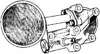
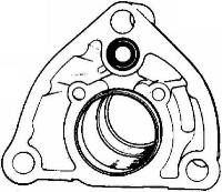
B/- WATER PUMP - Section Menu The water pump cannot be overhauled so must be replaced with a new part. C/ - OIL PUMP - Section Menu 1 - First type With ball valve and a two point fastening on the strainer flange. 2 - Second type. Important -
The strainer flange securing bolts are now 25 mm (63/64") long, instead of 20 mm (51/64"). They are made from grade YF 3 steel. The new covers are supplied complete with the pressure-limiting valve, the 25 mm (63/64") flange bolts, the gasket and locking plate.
NOTE -
New covers can be used to replace the type with ball valves, on condition that a curved bottomed sump (oil pan) is also fitted.
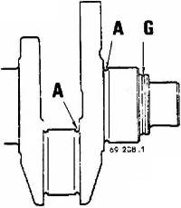
D/- CHECKING THE CONDITION OF THE CRANKSHAFT - Section Menu Crank pins (connecting rod journals) IMPORTANT.
The crankshaft main bearing journals and connecting rod journals are burnished at the locations indicated at (A) on the illustration. E/- CHECKING THE CAMSHAFT - Section Menu IMPORTANT
The sprocket is to be replaced by a new one each time it is removed. Do not refit roll pins.
Important note:
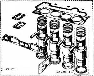
IF THE CAMSHAFT IS REPIACED THE DISTRIBUTOR DRIVE PINION MUST ALSO BE REPACED. F/- LINER - PISTON - CONNECTING ROD ASSEMBLY - Section Menu The liner and piston is sold as a matched kit.
Push in the gudgeon pin - mandrel - guide assembly by hand into the piston and the connecting rod small end, until the gudgeon pin makes contact with the connecting rod.
Important note.
The correct way round for the piston to be fitted is: Fit the following to the piston: IMPORTANT. As the gaps in all the piston rings are prepared, they are never to be adjusted.
Oil the piston rings, set them at 120º to each other with the gap in the oil control ring covering an unpierced section of its groove. G/ - CAMSHAFT FRONT BEARINGS - Section Menu H/ - CYLINDER BLOCK - Section Menu IMPORTANT E.7 - ASSEMBLING - Section Menu NOTE - Should it be necessary to replace the cylinder block, run-up the cylinder head securing bolts in their threads a number of times, in order to work in the threads.
NOTE - Tool (Part No 46E 6364) must be kept in a box and the face on which the seal lip locates should have no ragged edges on it. The projection should be between 0.14 and 0.19 mm (.005 to .0075").
Take the reading on two opposite sides of the diameter: if the difference between these two figures is greater than 2/100 mm (.001"), turn the liner half a turn and repeat the operation.
Seals can be obtained in three [2] different thicknesses: NOTE: The filter is 20.5 mm (13/16") long for tensioners with a backplate 2 mm (.079") thick, and 19.5 mm (49/64") long for tensioners with a backplate 1 mm (.040") thick.
REFITTING THE CYLINDER HEAD. NOTE - The cylinder gasket is sold together with the tappet compartment gasket.
- Engines - U.S.A. Federal Specification. [5] l/- Position the cylinder head gasket Engines - U.S.A. Federal Specification. NOTE - Fit only oil filters which have a crimped seal.
E.8 - REMOVING THE CYLINDER HEAD - REPLACING THE GASKET AND REFITTING THE CYLINDER HEAD - Section Menu A - REMOVING. Cylinder head removal operation. B - CLEANING THE GASKET FACES C - REFITTING. D - IMPORTANT NOTE. E.9 - REPLACING A VALVE SPRING - Section Menu E.10 - REPLACING THE MANIFOLD GASKET - Section Menu E.11 - REPLACING THE OIL FILTER - Section Menu E.12 – REMOVING AND REFITTING THE OIL PUMP STRAINER COVER - Section Menu A/- REMOVING. B- REFITTING. E.13 - OVERHAULING THE TIMING GEAR - Section Menu A/- Dismantling ADDITIONAL INFORMATION
E.14 - ENGINE MOUNTINGS - Section Menu New engine mountings (Part No. 054 E 6000) have been introduced as a running change into current production, and consequently no chassis number introduction is available. The new mountings lower the engine by approximately ½ in.
This engine lowering is particularly important when a radio suppression kit is fitted in conjunction with a radio (see Section 'M'), as the screening plate over the engine could foul the air cleaner.
E.15 - CRANKSHAFT SPROCKET - Section Menu Commencing at Engine No. 2557 Non-Emission, and 1255 Exhaust Emission, a new crankshaft sprocket (Part No. A046 E 6072) which is a press fit on the crankshaft has been used.
The bolt (Part No. A046 E 6012), washer (Part No. A046 E 6074) and spacer (Part No. A046 E 6C73) are no longer required in the new application.
Editors Notes: Other Notes: [edit]
Distributor - spark plugs - fuel pump - oil pressure switch - alternator bracket - oil filter - temperature switch - manifold assembly - the with its heating pipes - the water pump pulley - the clutch- the engine mounting plates.
Drain the engine oil.

Mark the position of the clutch assembly relative to the flywheel.
Remove the clutch assembly securing bolts.
Remove the clutch assembly and the driven plate.
Remove the distributor by undoing the clamp at the base of the distributor body and lift it from the engine complete with cap and plug leads.
Remove the fuel pump by undoing the two nuts at the mounting flange of the unit.
Remove the oil filter if still in position using special tool (Part No 46E 6432).
Remove the oil pressure switch by using tool (Part No 46E 6355).

Remove the left hand side engine mounting bracket.
Remove the dipstick.
Remove the carburetor and its heating pipes.
Remove the manifold assembly.

Fit support (Part No 46E 6302) to the adjustable stand.
Secure the three fastening rods to the engine.
Mount the engine on support (Part No 46E 6362).
Drain the oil.
Remove the rocker arm cover.
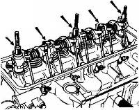
Remove the rocker arm assembly securing nuts and bolts.
Remove the rocker arm and the push rods (put them aside in the correct order).
Remove the cylinder head from the cylinder block:
As this operation is a very delicate one we request that you carefully follow the method described.
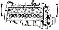
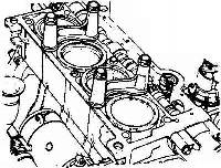
As the cylinder head gasket may be found to adhere to both the cylinder head and the cylinder block and liners, it is very important not to attempt to lift or prise the head.
The cylinder head should be pulled with a turning movement around the locating dowel on the distributor side to free it from the cylinder block.
Carry out the cylinder head removal operation:
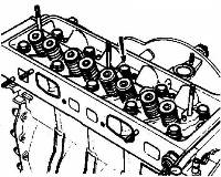
Loosen the securing bolts and remove them except for the one in the centre on the distributor side: this one is used as a pivot pin and also prevents the cylinder head rising.
Free the cylinder head by tapping its ends horizontally, with a plastic mallet.
Slightly lift the cylinder head and remove the tappets, (put them aside in the correct order).
Remove the cylinder head.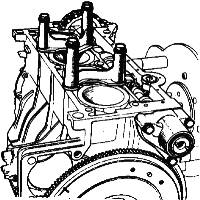
Remove the rubber gasket.
Fit the liner retaining clamps (Part No 46E 6352).
Remove the oil pump and distributor drive pinion.
Remove the three camshaft front bearing securing bolts.
Remove the bearing.
Turn the engine unit over.
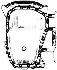
Remove the bolts, which secure the sump (oil pan) and remove it.
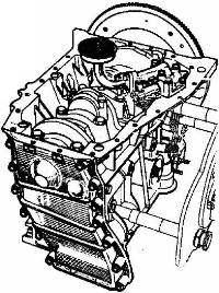
Remove the bolts securing the oil pump cover and remove the cover.
Take out both rotors.
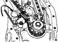
Remove the bolts securing the timing gear casing and remove the casing.
Remove the chain tensioner as follows:
- Unlock and unscrew the retaining cylinder screw.
- Insert a 3 mm. socket key into the retaining cylinder.
- Turn the key in a clockwise direction until tension is removed from the pad carrier assembly.
- Remove the tensioner.
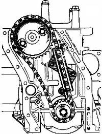
- Remove the crankshaft sprocket retaining bolt and the washer and thrust ring.
- Remove the lug, or lugs, which prevent the chain flailing.
- Remove the two bolts, which secure the camshaft flange.
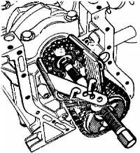
- Remove the crankshaft sprocket chain assembly, using extractor (Part No 46E 6434) whilst pulling back the camshaft.
- Remove the camshaft.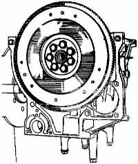
Unlock and unscrew the flywheel securing bolts.
Remove the flywheel.
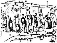
Check that the connecting rods are correctly marked.
It will be noted that their markings are in the reverse order to usual, i.e., No 1 is at the clutch end and to the camshaft.
Remove the big end nuts.
Remove the caps and the shells.
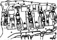
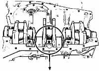
Mark the crankshaft main bearings with reference to their position on the cylinder block.
Unscrew the main bearing cap bolts.
Remove the bearings with the exception of the front bearing and the bearing shells.
Push out the front bearing in an upwards direction by tapping lightly on its two lower ends.
Remove the seal.
Take out the front bearing side seals.
- the crankshaft.
Remove the liner retaining washers.
- the shells.
- the end float thrust bearings.
Take out the "liner - piston - connecting rod" assemblies.
Remove the oil pump drive aperture cover panel.
Remove the cylinder block from its support.
1) - Dismantling.
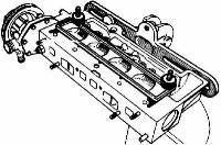
Take out the spark plugs.
Fit the cylinder head:
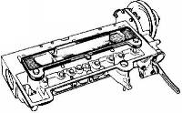
- either to support (Part No 46E 6435) which is fitted to the adjustable stand or the bench socket.
- or to plate (Part No 46E 6436)which is gripped in a vice.
- the water pump pulley,
- the water pump and its backplate complete with the alternator tensioner.
- the alternator bracket.
- the temperature sender unit.
Compress the valve springs:
Remove the collets, the springs and the seat washers.
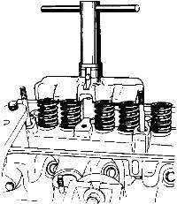
- either by means of multiple compressor (Part No 46E 6437).
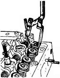
- or single compressor (Part No 46E 6438) after temporarily refitting the rocker arm assembly.
Remove the cylinder head from its support.
Take out the valves and put them aside in the order in which they were removed.
Dismantle all the rocker arm assembly components.
The plugs at the end of the shafts are force fitted and cannot be removed.
Carefully clean all parts.
a)- Cylinder head gasket face:
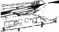
Check with a ground straight edge:
Maximum permissible distortion: 0.05 mm (0.002").
Reface it if necessary.
The maximum permissible thickness of metal that can be removed is: 0.3 mm (.012").
If more than this dimension, the cylinder head MUST BE REPLACED.
b) - Valve seats.
Standard seat widths:
Inlet: 1.3 (+0.3) (-0) mm (.051 to .063")
Exhaust: 1.7 (+0.3) (-0) mm (.067 to (.079")
Re-cut the valve seats if necessary using a 45° valve cutter, and grind the valves on their seats.
NOTE: Carefully clean the cylinder head after recutting the seats and grinding in the valves.
Remove all traces of swarf and grinding paste from ports and guides.
This operation is carried out with the aid of the following special tools:
![]()
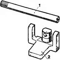
extracting and inserting tool: (Part No 46E 6440) which consists of:
an extracting and inserting mandrel (1).
a guide stop (2).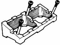
Place the cylinder head on spacer (Part No 46E 6441).
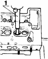
Push out the guide on the press using mandrel (1).
Measure the outside diameter of the guide to check whether it is the original one and whether it has already been replaced by an oversize part.
Replace the worn guide by one of the sizes immediately above it.
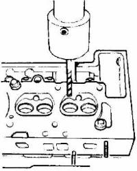
Ream out the guide locating bore with the reamer (Part No 46E 6442) which corresponds to the diameter of the new guide.

Fit the mandrel (1) into the guide stop (2), ensuring that this is fitted the correct way round depending whether the guide in question is an inlet guide or an exhaust guide.
Place the guide on the end of the mandrel (1) and the chamfer on the guide towards the outside.
Oil the guide.
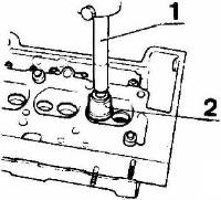
Place the assembly on the cylinder head and push in the guide on the press:
When the shoulder of the mandrel (1) has almost made contact with the guide stop (2), turn the guide stop until the shoulder actually touches.
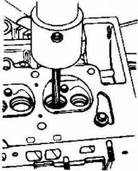
Ream-out the inside of the guide with reamer (Part No 46E 6442).
NOTE: After replacing a valve guide re-cut the corresponding valve seat (angle 45º).
Oversize tappets can be obtained in order to affect a repair.
Normal size: 12 mm (.473") - Repair size: 12.2 mm (.480").
The tappet location in the cylinder head must therefore be reamed out if the tappets are to be replaced.
Place the cylinder head on spacer, (Part No 46E 6441).
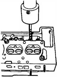
Ream-out the tappet bore using reamer (Part No 46E 6443) mounted in a drilling machine.
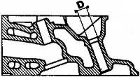
Check the diameter (D) of the counterbore at the top of the tappet bore: its diameter should be D 13 mm.
If it is less than this, it is to be opened up to 13 mm.
It is permissible to have thread inserts fitted to any of the tapped holes in the component.
When fitting thread inserts to the sparking plugs bores, take care to grind off the 2 or 3 threads which project into the combustion chamber.
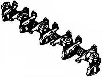
Fit the following to the rocker arm shaft ensuring that they are in the correct position.
the rocker arm assembly supports.
The lubrication holes in the shaft must face towards the push rod side.
- the rocker arms.
- the springs.
- The holes in the supports must be in line with those in the shaft.
Fit the valves in the correct order and secure the cylinder head:
- either to support (Part No 46E 6435)
Fit the valve spring seat washers, the valve springs and the collets
- or to plate (Part No 46E 6436).
Compress the springs by means of:
Fit the collets.
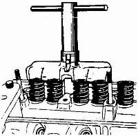
- either the multiple compressor (Part No 46E 6437)
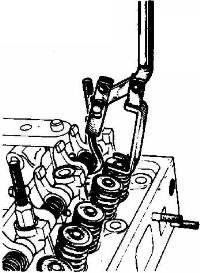
- or single compressor (Part No 46E 6438) after temporarily refitting the rocker arm assembly.
Fit:
- the water pump with its gasket (dry). .
Fit the alternator bracket.
- the alternator tensioner.
- the water pump pulley.
- the temperature switch.
a)- Dismantling
Unlock and unscrew the relief valve cap.
b)- Checking
Remove the spring, the guide and the ball.
Remove the two strainer pump securing bolts.
Clean and check all parts.
c)- Carry out the dismantling operations in reverse.
Check the inner and outer rotors for wear by placing them in a cylinder block.
Should any of the parts show signs of damage or wear the unit should be replaced as a complete assembly.
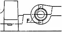
Check the clearance in the two positions shown below.
If these dimensions do not fall within the tolerances, replace both rotors (the inner rotor is supplied together with its shaft).
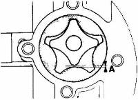
Position 1:
Dimension A: min. 0.04mm (.002") - max. 0.29 mm (.012")
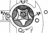
Position 2:
Dimension B: min. 0.02 mm (.001") - max. 0.14 mm (.006")
Check:
- the condition of the ball seat.
- the strainer flange gasket face to ensure that it is flat; reface it if it is not.
- the pump cover gasket face to ensure that it is flat; reface it if it is not.
Do not tighten the relief valve plug until having tightened the bolts on the strainer assembly flange.
NOTE - A special repair strainer is available with an increased depth.
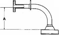
A 75 mm (2 31/32") replacement.
A 70 mm (2 3/4") production.
This is to be fitted to the pump in cases where the original flat bottomed sump (oil pan) has been replaced by a curved bottom type.
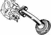
With a piston type relief valve and a three-point securing strainer flange.
a) - Dismantling
Unlock and unscrew the strainer bolts.
b) - Checking
Remove the relief valve retaining pin, and take out:
- the cup
- the spring
- the spring guide
- the piston.
Parts involved are identical to those used in the first type pump. However, the plug screwed into the cover is to be checked.
c) - Reassembling
- if the plug has a hexagon socket in it, no operation is to be carried out.
- if the plug has no hexagon it is to be replaced.
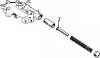
Place the following in the cover: the piston, the spring guide (with the head (T) inside the piston), the spring, and the spring cup.
Fit the retaining pin.
Fit the liner flange gasket: fit only the "Reinzolit" type gasket.
Fit the strainer, the single piece locking plate and tighten the bolts to a torque of 1.25 to 1.75 m.da N (10 to 15 lb/ft).
The tightening torque for these bolts is 2.25 to 2.75 m.da N (15 to 20 lb/ft). The fitting of longer bolts has involved increasing the length of the thread in the cover. The new bolts are, therefore, not to be used in old type pumps.

Remove the clutch spigot bearing by means of extractor (Part No 46E 6351).
Clean the crankshaft and pass a steel wire down the lubrication holes.
Check the crank pin and journal diameters with a micrometer.
Nominal diameter: 48 mm (1.890")
Regrind diameters for repair size bearing shells:
0.25 mm (.010")
Grinding: 0.018 mm (.0007') - 0.002 mm (.0001").
0.50 mm (.020")
Main bearings
Nominal diameters: 54.8 mm (2.158").
Regrind diameters for repair size bearing shells:
0.25 mm (.010")
Grinding: 0.013 mm (.0005") - 0.007 mm (.0003")
0.50 mm (.020")
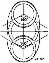
If the crank pins are machined, the burnishing must remain intact in a 140° zone facing the crankshaft centre line, as illustrated.
Groove (G) identifies the end of the crankshaft closest to the timing chain side of the engine block.
Fit the clutch spigot bearing with the seal towards the outside.
NOTE - As the bearing is supplied pre-greased, it must not be cleaned.
Remove the two pulley drive pins.
Clean it.
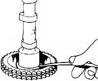
Check the clearances at the flange using a set of feeler gauges:
0.05 to 0.12mm (.002 to .0045").
This clearance cannot be adjusted so if it is not correct, replace the flange.
To do this:
Fit the new flange.
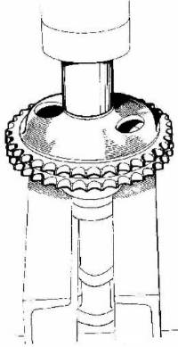
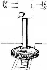
Push on a sprocket on the press taking the load on the first camshaft shoulder.
Check the clearance again.
Remove the "Piston - connecting rod" assembly from the liner.
Remove the piston rings.
The gudgeon pin is a force fit in the connecting rod and a running fit in the piston.
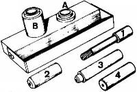
Separate the connecting rod from the piston, using tool (Part No 46E 6361), which comprises:
- the support base with 2 guides for extracting (A) and inserting (B).
- an inserting mandrel (1).
- a locating guide (2).
- an extracting mandrel (3).
- a dummy gudgeon pin (4) for checking the connecting rod.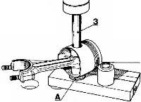
1) - Extracting the gudgeon pin.
Remove the pin on a hydraulic press using:
- the short guide (A) on the support base.
- the extracting mandrel (3).
2) - Inserting the new gudgeon pin.
a/ - Preparing the connecting rod.
Check the condition of the connecting rod by means of the dummy gudgeon pin (4).
Straighten the connecting rod and remove any twist.
Before assembly, place the connecting rod in a container of water. Heat the water until it boils.
NOTE - Using an electric oven providing temperatures up to 250 c (482 F) is even better than using boiling water.
b/ - Preparing the gudgeon pin.
Ensure that the gudgeon pin turns freely in the corresponding new piston.
Slide the new gudgeon pin onto the inserting mandrel.
Screw locating guide onto mandrel (1) until it makes contact with the gudgeon pin.
Do not tighten it.
Oil the gudgeon pin with a graphited oil.
c/ - Inserting the gudgeon pin into the connecting rod.
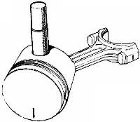
The following operations are to be carried out quickly so that the heat loss is reduced to a minimum (especially when the components have been heated by the boiling water method).
- with the arrow of the piston pointing downwards.
- with the number on the connecting rod big end facing towards the right, when the operator is standing facing the crown of the piston.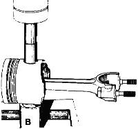
Fit the assembly into the inserting guide (B) on the base, ensuring that the spot-face on the piston is correctly located against the guide collar.
Push in the "mandrel - gudgeon pin - guide" assembly on the press until the locating guide makes contact with the bottom of the inserting guide.
NOTE - The depth of the bore in the guide has been calculated to correctly centralize the connecting rod on the gudgeon pin after insertion.
- the U-flex oil control ring.
- the compression ring.
- the “firing" ring.
As the cylinder block is made from pressure die cast aluminium alloy, the following precautions are to be taken when cleaning it:
- never scrape the upper gasket face.
- dissolve any remaining portion of the cylinder head gasket which is sticking to the cylinder block with Trichlorethylene.
- do not scrape the liner locating areas.
- remove any oil which remains in the cylinder block front securing hole on the camshaft side.
The plug plates (core plugs) are not to be removed,
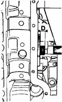
- check the projection (D) of the stud to which the oil filter is fitted above the sealing face of the cylinder block D 9.5 to 12.5 mm (3/8 to ½").
If it is less than 9.5 mm (3/8"), the stud must be replaced by another repair size stud, which is 41 mm (l 3/8"), long.
Adjust its length to obtain the correct projection.
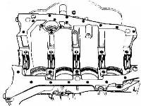
Fit the cylinder block support (Part No 46E 6362).
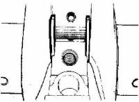
Fit the main bearing shells: they have lubrication holes in them.
Oil the shells.
Oil the crankshaft journals and fit them in place.
Fit the end float shims (with the machined face towards the crankshaft).
Fit the bearing shells to main bearing caps) numbers 2 - 3 - 4 and 5: they have no lubrication holes in them.
Oil the shells.
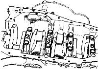
Fit the main bearing caps by following the position marks made during dismantling.
Fit the bolts: do not tighten them.
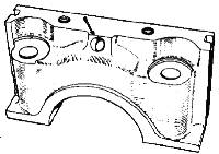
Check the diameter of the oil drain hole in the front main bearing cap.
If this is 8 mm (.315"), it must be increased in diameter to 12 mm (. 472").
Carefully de-burr the edges of the holes.
Fit the shell to the front bearing cap.
Temporarily fit the front bearing cap and tighten the bolts.
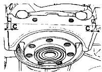
Measure dimension C between the cylinder block and the bottom of the bearing seal locating groove.
If dimension C is less than 5 mm (.197") select 2 seals 5.10 mm (.201") thick.
If dimension C is greater than 5mm (.197"), select 2 seals 5.35mm (.211") thick, which have a white colour code.
Remove the bearing cap.
Fit the two side seals to the front bearing cap:
- with the groove in the seal towards the outside,
Oil the shell and the side seals.
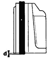
- the seal projection above the locating faces on the cylinder block side (d = 2/10 mm approximately (.008").
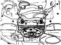
Screw two locating studs (diameter 10mm, pitch 150), into the cylinder block.
Fit the front bearing caps to the studs:
-Fit two shims between the cylinder block and the seals in order not to damage the seals.
When the cap is almost in position, ensure by means of a rule that the side seals still project slightly.
Remove the shims and the studs and fit the bolts.
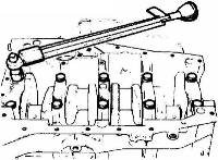
Tighten the bearing cap securing bolts to a torque of 6.5 m.da N (45 lb/ft) using torque wrench (Part No46E 6353).
Check that the crankshaft turns freely.
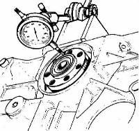
Fit a dial indicator at the end of the crankshaft.
Check the crankshaft end float: it should be between 0.05 and 0.23 mm (.002” to .009").
If this play is incorrect, replace the end float at adjusting flanges.
These are obtainable in several different thicknesses:
- nominal thickness: 2.80 mm (.110")
- repair thickness: 2.90 mm (.114")
- repair thickness: 2.95 mm (.116")
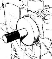
Fit the seal by lightly tapping the end of the tool, until it makes contact with the crankshaft.
Protect the tool in storage with a worn out seal.
Fit the flywheel.
Apply a maximum of one or two drops of "Loctite" locking compound on the securing bolt threads.
repair thickness:Fit the locking plate and screw down the bolts. As these bolts are of the self-locking type, they are to be replaced by new ones every time they are removed.
The locking plate is also to be replaced
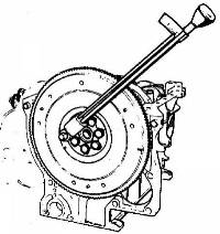
Tighten the bolts to a torque of 5 m.da N (40 lb/ft) using torque wrench (Part No 46E 6353).
Fold up the locking plate with a pair of pliers: only fold the plate onto one of the hexagon flats on each bolt.
Fit the lower seals to the liners using a thin blade with carefully rounded edges: the seals are to be 0.07 mm (.003") thick; these are identified by a blue colour code.
Fit the liners into the cylinder block.
Press on the liners by hands to ensure that they locate correctly on the seals.
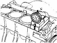
Check the extent to which the liners project above the cylinder block face using thrust plate (Part No 46E 6359) and the dial indicator support (Part No 46E 6358). The dial container must be fitted to extension (part No 46E 6444).
0.07 mm (.003") blue colour code,
0.10 mm (.004") red colour code,
0.13 mm (.005”) green colour code. [3]
Repeat this operation for the other liners.
Mark the position of the liners with reference to-the cylinder block so that they may be re-fitted to the same position on final assembly:
Make the marks on the camshaft side.
Remove the liners.
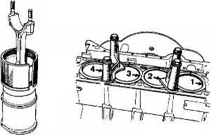
Oil the pistons.
Fit the "piston-connecting rod" assemblies into the liners using sleeve (Part No 46E 6354).
Fit them in the correct position.
- The number marked on the connecting rod big end is to be on the camshaft side, that is to say, on the same side as the reference mark made when checking the liner projection.
- The big end faces on the connecting rods are to be parallel to the flats on the tops of the liners.
Fit the shells to the big ends.
Fit the "connecting rod-piston-liner" assemblies into the cylinder block in the correct positions:
- With number 1 at the clutch end.
Fit the liner retaining flanges (Part No 46E 6352).
- With the arrow on the piston pointing towards the clutch end.
- With the number on the big end on the camshaft side.
- With the mark on the liner in line with that made on the cylinder block.
Turn the engine over.
Place the connecting rods on the oiled crank pins.
Fit the big end caps together with their shells, ensuring that they are on the correct connecting rods.
Fit the cap nuts.
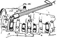
Tighten the nuts to a torque of 4.5 m.da N (30 lb/ft) using a torque wrench (Part No 46E 6353).
Check to ensure that the moving parts rotate freely.
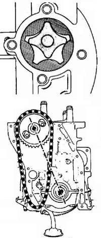
Fit the outer rotor and then the inner rotor to the oil pump.
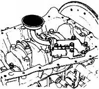
Fit the oil strainer cover and secure it.
Turn the engine over.
Oil the camshaft bearing areas and fit it in position: do not push it fully home.
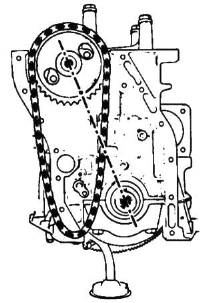
Place the chain over the camshaft sprocket: align the mark on the sprocket, with the centre of the crankshaft and the centre of the camshaft.
Turn the crankshaft to bring the key to the uppermost position.
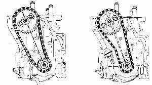
Fit the crankshaft sprocket (with the reference mark towards the outside) on the chain:
the reference mark is to be in line with that on the camshaft sprocket, and with the camshaft and crankshaft centres.
With the references in line, fit the sprocket to the crankshaft: fit it by means of a tube gradually pushing the camshaft into position.
When the chain is correctly tensioned, the line between the two reference marks no longer passes through the centre line of the camshaft drive.
Fit the spacer, the thrust washer and the crankshaft sprocket bolt.
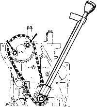
Tighten the bolt to a torque of 6 m.da N (45 lb/ft) using a torque wrench (Part No 46E 6353).
Fit and tighten the two camshaft flange bolts.
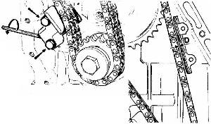
Fit the chain tensioner (together with its filter) and its backplate.
Tighten the two bolts.
Insert a 3 mm (.118") socket key into the retaining cylinder.
Turn the key in an anti-clockwise direction until the pad carrier assembly is projected against the chain.
Tighten and lock the bolt on the retaining cylinder.
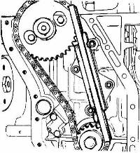
Fit the flail limiting lug (or lugs if the engine is fitted with two) so that it is parallel to the chain.
When the chain is correctly tensioned it should be at a distance D = 0.8 mm (.032") from it.
If the engine is fitted with two lugs:
Fit the two lugs and place the gauge (Part No 46E 6445) on the chain.
Push the two lugs against the gauge and tighten their securing nuts.
Remove the gauge.
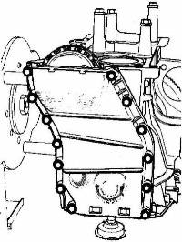
Fit the timing gear casing with its gaskets smeared with jointing compound (Ref.805 463).
Fit the bolts and align the upper edge of the casing with the upper edge of the cylinder block.
Tighten the bolts.
Turn the engine over.
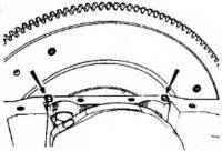
Cut off the two front bearing seals flush with the cylinder block.
Fit the sump (oil pan): the two shortest bolts are screwed into the front bearing.
Turn the engine over.
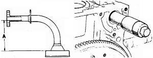
If a later type sump with a curved bottom (available only as a spare) is to be fitted to an old type engine, the old pattern oil pump strainer (height A 70 mm.) (2¾") must be replaced by a special repair size strainer (height A 75 mm) (2 31/32").
Fit tool (Part No 46E 6363) to the end of the camshaft to lift the lips on the bearing seal.
Secure it in place by means of the camshaft pulley bolt.
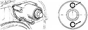
Ensure that the "O" ring seal on the lubrication ducting is correctly fitted to the bearing casing.
Fit the camshaft bearing casing together with its paper or Excelnyl [4] gasket:
Secure it in place by means of three bolts.
Fit the two pins, which drive the pulley: push them slightly in; they are finally fitted when the pulley is tightened into place.
Fit the pins as shown in the illustration.
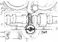
Turn the engine until No. 1 cylinder is in the firing position (the cams on No. 4 cylinder are then in balance).
Fit the oil pump and distributor drive pinion, ensuring that it is correctly positioned:
- with the slot parallel with the engine longitudinal centre line, and
Fill the camshaft cavity in the cylinder block with engine oil.
- with the smallest off-set on the camshaft side.
Remove the liner retaining flanges; then refit the cylinder head.
The operation of correctly positioning the cylinder head and its gasket is a very important one. It is this in fact that determines the distributor drive shaft alignment with the drive pinion. If this should be necessary (as a result of incorrectly positioning the cylinder head, for example), it is not to be used again.
1) - Position the cylinder head gasket.
- Engines - European Specification.
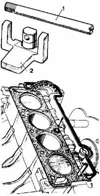
Positioning tool set (Part No 46E 6423) is required for this operation and consists of:
- 1 gasket locating dowel (1).
- 1 cylinder head locating gauge (2).
Fit the gasket locating dowel (1) at the clutch end of the cylinder block, at the camshaft side.
Ensure that the cylinder head locating dowel bush is in fact in position in the block.
Fit the gasket: once it is in place, it is not to be removed.
Fit the rubber gasket round the tappet compartment, avoiding overlapping the cylinder head gasket at the ends.
This gasket is only to be fitted to cylinder blocks with 9 holes and to timing gear casings with 4 holes.
If it is fitted to a timing gear casing with 2 holes, cut off the two excess studs flush with the gasket.
Fit the tappets to the cylinder head in the correct order: lightly tap them so that they stick into their locations.
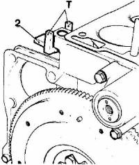
Fit the gauge (2) into the upper hole of the cylinder block at the clutch end with the two lugs (T) parallel with the longitudinal centre line of the engine.
Position the cylinder head and place it on the cylinder block:
before it makes contact with the cylinder head place the manifold locating face against the two lugs (T) on gauge (2).
Take care not to move the tappet compartment gasket.
From this point onwards, do not touch the cylinder head.
Remove the locating dowel.
Lightly lubricate the cylinder head bolts with engine oil.
Fit the bolts and screw them slowly in.
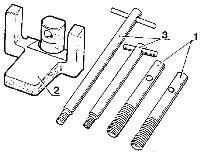
Additional tools and dowels different than those in positioning set (Part No 46E 6423) are specified for U.S.A. Federal engines.
This set (Part No 46E 6422) consists of:
- 2 positioning dowels (1).
- 1 cylinder head locating gauge (2).
- 2 tee handles (3) - Use only the shorter one.
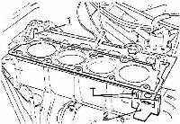
Slide side-gauge (2) into the engine block hole located on the cylinder side of the engine block at the clutch end [9], with the two prongs (T) uppermost and parallel with the engine block centre line.
Be sure that the cylinder head positioning sleeve (indicated by the arrow in the illustration) is in place on the top of the engine block.
Install the cylinder head gasket:
Once it is installed DO NOT remove it.
If the gasket must be removed (because the cylinder head was not correctly positioned, for instance), discard it and use a new one.
Install the positioning studs (1) as illustrated, and screw them in until the spring-loaded balls apply just enough pressure on the cylinder head gasket to keep it flat against the engine block.
Install the camshaft housing rubber gasket.
Be sure that its ends fit inside the corresponding cut-out portions of the cylinder head gasket and do NOT overlap it.
Install the cam followers in their housing, in the same order they were removed. Tap them lightly to keep them in place.
Check that the ignition distributor drive pinion is correctly positioned, as described on page 40. [6]
Slide the cylinder head slowly over the positioning studs.
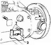
Before it makes contact with the cylinder head gasket, be sure that its manifold side is resting against the two prongs (T) of side-gauge (2).
Be careful not to disturb the camshaft housing rubber gasket.
Once the cylinder head has made contact with its gasket leave it undisturbed.
Lightly lubricate the threads of the cylinder head bolts with engine oil.
Install two bolts at the centre of the cylinder head and tighten them lightly.
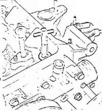
Use the short T-handle (3) to remove the positioning studs.
Install the remaining cylinder head bolts and tighten them lightly.
Do not forget to install the spacers beneath the heads of the two front bolts (closest to the timing chain end of the engine block).
2 - Tightening the cylinder head bolts.
The operation of tightening the cylinder head bolts is an important one, and there is a risk of leakage if it is incorrectly carried out.
This operation is to be carried out with great accuracy and the torques applied to the bolts must be carried out gradually.
We therefore forbid the use of "break back" release type torque wrenches for this operation. We request that you should only use direct reading torque wrenches, e.g., wrench (Part No 46E 6353).
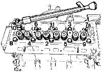
The bolts are to be tightened in 3 separate movements.
a) - First phase:
Tighten to 4 m.da N (30 lb/ft) in the order shown.
b.) - Second phase:
Tighten to 7.5 to 8 m.da N (55 to 58 lb/ft) after having loosened the bolts by ¼ of a turn.
Ensure that the tightening order is followed correctly and that the torque is accurate. Pull the bolts up smoothly without jerking them.
c.) - Third phase.
The third operation is to be carried out after the engine is fitted to the vehicle.
Start the engine, allow it to warm up for 10 minutes, then switch off and allow it to cool for 50 minutes.
Remove the rocker arm cover.
Loosen the bolts by ¼ of a turn and re-tighten them to 8.75 m.da N (63 lb/ft).
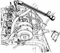
NOTE -
For the first 8 bolts, use a torque wrench extension (Part No 46E 6447).
For the last 2 bolts, use wrench (Part No 46E 6360) with crank extension piece (Part No 46E 6446).
Because of this cranked tool the tightening torque on this is to be reduced by 10%. i.e.: 7.5 to 8 m. da N (55 to 58 lb/ft).
Fit the push rods and the rocker arm assembly. Make sure that the two end supports locate correctly on their dowels.
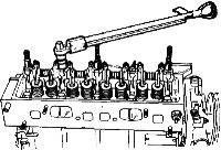
Tighten the rocker arm assembly securing nuts to a torque of 2 to 2.75 m.da N (15 to 20 lb/ft) using a torque wrench (Part No 46E 6353).
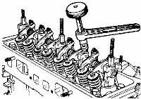
Adjust the rocker arm clearance by means of spanner (Part No. 46E 6356):
- inlet: 0.20 mm (.008")
As the tappets are fitted in the cylinder head it is possible that they will stick slightly in their locations.
- exhaust: 0.25 mm (.010")
Before adjusting each rocker arm lightly tap the adjusting screw, to make sure that the tappet is in fact resting on the camshaft.
Refit the distributor and temporarily adjust its static timing.
Fit the plugs and connect up the leads.
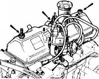
Refit the rocker arm cover ensuring that the positioning lugs are correctly located inside the cylinder head
Check that the manifold face is flat: maximum permissible distortion 0.20 mm (.008").
Fit the manifold gasket.
Fit the "manifold" assembly: allow it to assume its correct position under its own weight.
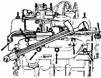
Tighten the securing nuts and bolts to a torque of 1.5 t0 2.5 m.da N (l0 to 20 lb/ft) by means of torque wrench (Part No 46E 6353).
Connect the heating pipes between the bottom of the and the cylinder head: use key (Part No 46E 6448) to tighten the clips.
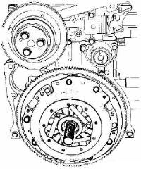
Fit the clutch driven plate with the off-set on the hub towards the transmission;
the clutch assembly, when applicable, following the position mark made during dismantling.
Centralise the driven plate by means of mandrel (Part No 46Q 6006).
Tighten the clutch assembly securing bolts.
Remove the engine from the stand (Part No 46E 6362).
Fit:
- the oil pump drive shaft location cover plate.
- the side mountings.
- the oil pressure switch: special tool (Part No 46E 6355)
- the dipstick.
- the oil filter: oil the seal with engine oil.
- screw in the filter until the seal makes contact with the housing.
- tighten the filter, by hand, through a ¼ of a turn. The reference marks l, 2, 3 and 4 will make this operation easier.
- unscrew it and retighten it by between ½ and ¾ of a turn.
fit the fuel pump.
Disconnect the battery cables (earth lead first).
Remove the rear luggage compartment by undoing the two bolts set in the floor of the unit. Take care to note the quantity and position of the spacer washers situated between the cross member and the under surface of the compartment.
Drain the cooling system (see section K).
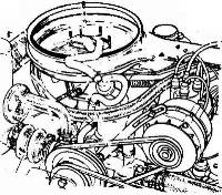
Remove the air filter from the carburetor.
- the plug leads (including the coil lead).
Remove the distributor.
- the distributor input leads.
- the vacuum pipe at the distributor.
- the alternator leads.
Release the alternator belt tension and remove the alternator.
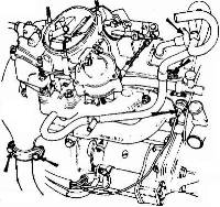
Undo the two bolts of the exhaust pipe clamp at the manifold connection.
Remove the clamp.
Undo the clamp at the front of the silencer (muffler) and swing the down pipe clear.
Remove the emission capsule and its hose.
Disconnect the temperature switch lead on the cylinder head.
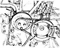
Disconnect the heater hoses at the control valve and the radiator hoses at the water pump.
Remove the nuts, which secure the pulley.
Remove:
- the outer flange.
Remove the heater hose clip on the rocker arm cover (if fitted).
- the adjusting shims.
- the drive belt.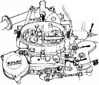
At the carburettor disconnect:
- the lead from the solenoid valve.
Remove the 'E' clip from the accelerator quadrant post situated on the top of the rocker arm cover.
- the vacuum pipe.
- the choke wire.
- the accelerator return spring.
- the fuel pipe.
- the accelerator cable.
Lift off the quadrant.
Remove the nuts and washers securing the carburettor to the manifold.
Remove the carburettor and gaskets.
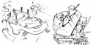
If the exhaust manifold gasket is to be replaced at the same time -
Remove the manifold.
Undo the four nuts and washers and the two socket bolts and washers, retaining the manifold to the cylinder head. Carefully remove the manifold and the gasket.
Undo the three nuts securing the rocker arm cover and remove the cover.
Undo and remove the nuts and bolts securing the rocker arm assembly.
Remove the rocker arm assembly and the push rods (put them aside in the order in which they were removed).
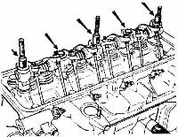
As the cylinder head gasket sticks to the cylinder head, cylinder block and liners, it is very important that you should not lift the cylinder head, which would cause the liners to come unstuck at the bottom, and result in dirt entering and damage to the lower seals.
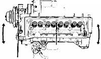
The cylinder head is to be twisted horizontally around the locating dowel on the distributor side to free it from the cylinder block.
To remove the cylinder head:
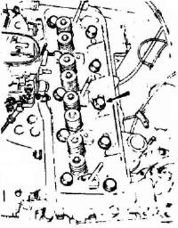
Loosen the securing bolts and remove them except for the centre bolt on the distributor side: This is used as a pivot point and to prevent the cylinder head rising.
Free the cylinder head by tapping its ends with a plastic mallet to impart a horizontal rotating movement.
Remove the centre bolt.
Partly lift the cylinder head, remove the tappets (put them aside in the order in which they are removed).
Remove the cylinder head.
It is very important that the gasket faces on the cylinder block and the cylinder head should not be scraped with a sharp tool.
In fact, any distortion of this face however small, can cause leakage past the cylinder head gasket.
Use only Trichlorethylene to remove the part of the gasket, which remains sticking to the cylinder head and the cylinder block.
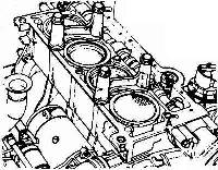
Check the liner projection: 0.12 to 0.19 mm (.006 to .0075").
Remove the oil in securing hole (A) at the rear on the camshaft side, by means of a syringe. This is necessary to be able to tighten the bolt correctly.
Clean hole (B) in the cylinder block with a rag.
Remove the liner retaining flanges.
1/ - Positioning the gasket and the cylinder head.
For this operation tool (Part No 46E 6423) is required.
This comprises:
- 1 gasket locating dowel (1)
- 1 cylinder head positioning gauge (2).
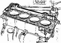
The operation of positioning the cylinder head is a very important one; in fact it ensures the alignment of the distributor drive shaft and the distributor drive pinion.
Screw the gasket locating dowel (1) into the clutch end of the cylinder block on the camshaft side.
Fit gauge (2) in the front hole of the cylinder block, with the two lugs (1) parallel with the engine longitudinal centre line.
Ensure that the cylinder head locating dowel is in fact in position in the cylinder block.
Fit the cylinder head gasket: Once this is in position, it is not to be removed.
Should it be so (if the cylinder head were incorrectly positioned for example) do not attempt to use it again.
Fit the tappet compartment rubber gasket, avoiding it overlapping the cylinder head at the ends.
Place the tappets in the cylinder head in the correct order and tap them lightly, so that they stick in their locations.
Ensure that the distributor drive pinion is in fact in position.
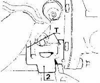
Position the cylinder head and place it on the cylinder block:
before it touches the cylinder head gasket place against the two lugs (T) on the gauge (2).
Ensure that you do not move the tappet compartment gasket.
From this point onwards, the cylinder head is not to be touched.
Remove the gasket locating dowel.
Lubricate the cylinder head bolt threads with engine oil.
Fit the bolts and screw them slowly in.
2/ - Tightening the cylinder head bolts.
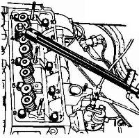
Tightening the cylinder head bolts is an important operation and leaks past the gasket may result if it is carried out incorrectly.
They are to be tightened with the highest possible degree of accuracy and the torque is to be applied to the bolts smoothly, without jerking them.
We therefore forbid tightening these bolts with a "break-back" release type torque wrench.
We request that you should use a direct reading torque wrench only.
The one we recommend is (Part No 46E 6353).
Furthermore, one must also have the following accessories:
an extension for the first eight bolts.
The bolts are to be tightened in three separate movements.
special wrench (Part No 46E 6360) for the last two bolts.
a/ - First phase:
Tighten to 4m.da N (30 lb/ft) in the older shown.
b/ - Second phase:
Tighten to 7.5 to 8 m.da N (55 to 58 lb/ft), after first loosening the bolts by ¼ of a turn. Ensure that the torque and tightening order are correct. If the bolts "jerk" and will not tighten smoothly and positively, they are to be screwed in and out a number of times.
NOTE – Use a 17 mm socket on the end of the wrench.
The third tightening phase is to be carried out after having run the engine.
Fit the push rods and the rocker assembly.
Make certain that the two end supports engage correctly on their locating studs.
Tighten the rocker arm assembly securing nuts and bolts to: 2 to 2.75 m.da N (15 to 20 lb/ft).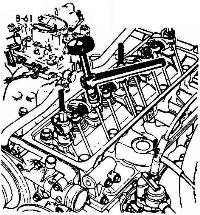
Adjust the rocker arm by means of tool (Part No 46E 6356): use the knurled nut to adjust the clearance and the lever to lock and unlock each adjuster lock nut.
Valve clearance on a cold engine:
- inlet: 0.20 mm (.008")
As the tappets are fitted in the cylinder head it is possible that they will stick slightly in their bores.
- exhaust: 0.25 mm (.010")
Before adjusting each rocker arm, lightly tap the adjusting screw to be sure that the tappet is resting on the cam.
Do not use the camshaft pulley securing bolt to turn the engine.
Therefore:
- lift one side of the vehicle.
Refit the manifold (if removed during these operations) using a new gasket of the correct type, which corresponds to the inlet parts of the manifold.
- engage 4th gear.
- rotate the driven road wheel in the forward drive direction.
Tighten the manifold nuts and socket bolts to a torque of 1.5 to 2.5 m.da N (10 to 20 lb/ft).
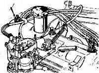
Refit the carburetor using a new gasket (see section L).
Secure the exhaust pipe clamp.
Refit the rocker arm cover.
Fit the accelerator idle lever.
Connect up:
- the accelerator cable and spring.
- the choke cable (when applicable).
- the lead to the temperature switch on the cylinder head.
- the fuel pipe.
- the vacuum pipe.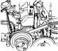
Connect the heater and radiator hoses to the water pump.
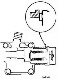
Check that the thermostat leakage hole is upwards and in line with the slot in the pump body.
Tighten the clips by means of key (Part No 46E 6433).
Secure the heater hose clip to the rocker arm cover.
IMPORTANT: Carefully remove any sharp edges from the ribs on the water pump ends in order to avoid damage to the hoses.
Refit the distributor, connect up the leads and set it to the static timing (see Technical Data).
Refit the alternator and connect up the lead.
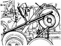
Fit the alternator drive belt and tension it.
Check its tension by means of tool (Part No 46M 6206).
The deflection should be: 7 to 9.5 mm (9/32" to3/8").
If the deflection is incorrect, adjust the belt tension.
Fit:
- the water pump drive belt adjusting shims.
Slowly tighten the outer flange securing bolts while turning the engine in order to avoid damage to the belt.
- the belt.
- the outer pulley flange.
NOTE - Under no circumstances should the camshaft pulley securing bolt be used to turn the engine.
One must therefore:
- Lift one side of the vehicle.
- Engage 4th gear.
- Rotate the driven road wheel in the forward drive direction.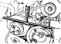
Check the belt deflection by means of tool (Part No 46M 6206): it should be between 2.5 to 4 mm (3/32 to 5/32").
If the deflection is not correct, add or remove shims between the two pulley flanges
Top up the cooling system.
Connect up the battery.
Start the engine and allow it to warm up for 10 minutes, then switch it off and allow to cool for 50 minutes.
Disconnect the battery.
Remove the rocker arm cover.
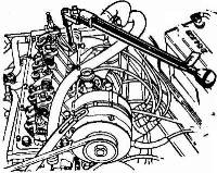
Loosen the cylinder head bolts by ¼ of a turn and retighten them to a torque of 8.25 to 8.75 m.da N (55 to 60 lb/ft).
NOTE - Use tool (Part No 46E 6360) and the cranked tool (Part No 46E 6446) for the last two bolts:
consequently the tightening torque of or these two bolts should be reduced by 10%, i.e., = 7.5 to 8 m.da N (55 to 58 lb/ft).
Adjust the rocker arm clearances:
inlet: 0.20 mm (.008")
Refit the rocker arm cover.
exhaust: 0.25 mm (.010")
Before tightening the securing nuts, ensure that the positioning tabs on the cover are correctly positioned on it.
Fit the emission capsule to the rocker arm cover. Refit the air filter.
Whenever the cylinder head gasket has been replaced one must, after 500 kms (300 miles):
- retighten the rocker arm assembly fastenings.
These operations can be carried out whether the engine is warm or when it is cold.
- retighten the cylinder bolts.
- adjust the rocker arms.
1 - When the engine is warm, 50 minutes after it has been switched off.
- Loosen the cylinder head bolts by ¼ of a turn.
2 - Allow the engine to cool, and 2½hours after the engine has been switched off:
Retighten them to a torque of: 8.75 to +0/-0.15 m.da N (63 lb/ft).
NOTE -
When using tool (Part No 46E 6360) and cranked tool (46E 6446) for the last two bolts, the tightening torque must consequently be reduced by 10%, i.e., 7.5 to 8 m.da N (55 to 58 lb/ft).
Tighten the nuts and bolts, which secure the rocker arm assembly to a torque of 2 to 2.75 m.da N (15 to 20 lb/ft).
Adjust the rocker arm clearances to:
- inlet: 0.20 mm (.008")
- exhaust: 0.25 mm (.010")
Loosen the cylinder head bolts by ¼ of a turn.
Retighten them to a torque of s 7.5 to 8 m.da N (55 to 58 lb/ft).
Disconnect the battery cables (earth lead first).
Remove the rear luggage compartment.
Remove the air filter.
Disconnect:
- the fuel pipe and the vacuum pipe from the .
Remove the heater hose clip if fitted to the rocker arm cover.
- the accelerator cable and spring.
- the choke cable.
Remove the 'E' clip from the accelerator quadrant post on top of the rocker arm cover and lift off the quadrant.
Remove the emission capsule and hose.
Remove the rocker arm cover.
Remove the spark plug, which corresponds to the valve spring, which is to be replaced.
Unscrew the rocker arm screw concerned and removed the push rod.
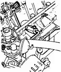
Fit the valve retaining clamp (Part No 46E 644g) in place of the spark plug.
Move the rod on the clamp so it rests under the valve head and tighten the rod in place.
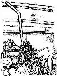
Compress the spring by means of compressor (Part No 46E 6438).
Remove the collets, the upper spring seat and the spring,
Carry out the removing operations in reverse to refit the valve spring.
Adjust the rocker arm by means of tool (Part No 46E 6356): use the small head for the end rocker arm.
Clearance:
- inlet: 0.20 mm (.008")
- exhaust: 0.25 mm (.010")
Disconnect the battery leads (earth first).
Remove the air cleaner
At the carburetor:
- the lead from the solenoid valve.
Remove the 'E' clip from the accelerator quadrant post and pull off the quadrant.
- the vacuum pipe.
- the choke wire.
- the accelerator return spring.
- the fuel pipe.
- the accelerator cable.
Remove the securing nuts and lift the instrument off.
Undo the two nuts on the clamp securing the down pipe to the manifold.
Remove the clamp.
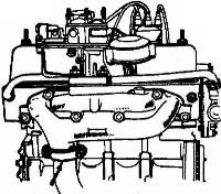
Undo the clamp securing the down pipe to the silencer (muffler) and swing the down pipe clear.
Undo the four nuts and two socket bolts and washers securing the manifold to the head.
Remove the manifold and gasket.
Clean the manifold faces.
Check the manifold gasket face.
Maximum distortion: 0.20 mm (.008").
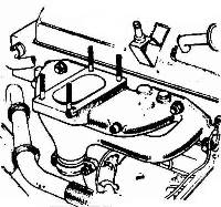
To refit the manifold, carry out the removing operations in reverse:
- Fit the gasket (of the correct type which corresponds to the inlet parts of the manifold).
- The metal face of the gasket should be against the cylinder head.
- Tighten the manifold nuts and socket bolts to a torque of: 1.5 to 2.5 m.da N (10 to 20 lb/ft).
- Run the engine for 10 minutes and allow it to cool for 50 minutes.
- Retighten the nuts and socket bolts to a torque of 1.5 to 2.5 m.da N (10 to 20 lb/ft).
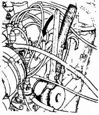
Loosen the filter by means of tool (Part No 46E 6432).
- pass the strap round the filter and insert it into the stirrup.
- tension it.
- loosen the filter.
- remove the tool and unscrew the filter by hand.
Check the filter spigot projection above the seal face on the cylinder block.
It should be: 9.5 to 12.5 mm (3/8 to ½").
If it is less than 9.5 mm (3/8"), replace it by another special repair size spigot.
Correct its length to obtain the correct projection (when applicable).
Oil the new filter seal with engine oil.
Screw in the filter until the seal makes contact with the locating area on the cylinder block.
Then tighten the filter by hand by ¼ of a turn: the reference marks 1 - 2 - 3 - and 4 on the can help one to carry out this operation correctly.
Unscrew the filter, bring it in contact with its locating base and retighten it by ½ to ¾ of a turn.
NOTE – Use only oil filters with crimped seals.
Run engine and check for leaks.
Place the car on a lift.
Drain the engine oil.
Remove the sump (oil pan).
Remove the pump strainer cover securing bolts and remove it.
Remove the outer rotor and inner rotor, with its shaft.
The inner rotor will come out entirely:
it is not necessary to remove the engine. [7]
Carry out the removing operations in reverse.
Fill the engine with oil.
Remove the engine and mount it on support (Part No 46E 6362).
Remove the:
- cylinder head
Remove the crankshaft sprocket retaining bolt and the washer and thrust ring.
- the sump (oil pan)
- timing gear casing
- camshaft front bearing.
Remove the anti-flail lug or lugs.
Remove the two bolts, which secure the camshaft flange.
Remove the chain tensioner as follows:
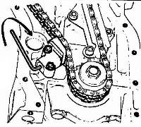
- Unlock and unscrew the retaining cylinder screw.
- Insert a 3 mm socket key into the retaining cylinder.
- turn the key in a clockwise direction until the pad carrier assembly is no longer under tension.
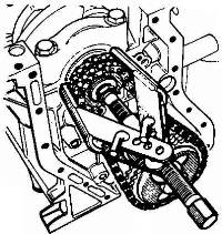
Remove the crankshaft sprocket and chain assembly using extractor (Part No 46E 6434) whilst pulling back the camshaft.
Remove the camshaft.
Oil the camshaft bearing areas and insert it: do not push it fully in.
Place the chain on the camshaft sprocket:
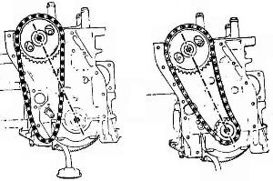
Align the reference on the sprocket with the centre of the crankshaft and the centre of the camshaft.
Turn the crankshaft to bring the key uppermost.
Fit the crankshaft sprocket (with the reference mark facing towards the outside) on the chain.
The reference mark is to be in line with that on the camshaft sprocket and the centre of the crankshaft and the camshaft.
When the reference marks are in line engage the sprocket onto the crankshaft: fit it by means of a tube while gradually pushing the camshaft into position.
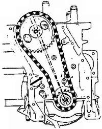
When the chain is correctly tensioned, the line passing through the reference mark is no longer directly in line with the camshaft centre.
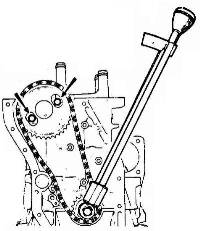
Fit the crankshaft sprocket spacer, thrust washer and bolt.
Tighten the bolt to 6 m.da N (45 lb/ft) using torque wrench (Part No 46E 6353).
Fit and tighten the two camshaft bolts.
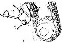
Fit the chain tensioner (together with its filter and its backplate.
Tighten the two bolts.
Insert a 3 mm (.118") hexagon socket into the retaining cylinder.
Turn the key in an anti-clockwise direction until the body carrier assembly is projected against the chain.
Tighten and lock the retaining cylinder bolt.
NOTE - The filter is:
- 20.5 mm (13/16") long for tensioners on which the backplate is 2 mm (.079"} thick
Fit the anti-fail lugs.
- 19.5 mm (49/64") for tensioners on which the backplate is 1 mm (.040") thick.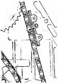
If the engine is fitted with one lug only, fit the lug so that it is parallel with the chain, when the chain is tensioned, at a distance: D = 0.8 mm (.032") from it.
If the engine is fitted with two lugs:
Place the two lugs against the chain and tighten the securing bolts.
Remove the gauge.
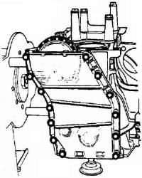
Fit timing gear casing with its gasket smeared with a jointing compound.
Fit the bolts and align the upper face of the casing with the upper face of the cylinder block.
Tighten the bolts.
Refit the:
- camshaft bearing
- sump (oil pan)
- cylinder head
- engine.
[1] Added 4) Tappet replacement – omitted in OEM Shop Manual. [SV]
[2] Three thicknesses are available, based on actual experience. [SV]
[3] Green colour code seals were measured July 1, 2007. [SV]
[4] This gasket material appears identical to the Excelnyl liner seals. [SV]
[5] Revised for clarity: either tool set can be used on either type engine. [SV]
[6] Added page 40 note based on importance of task. [SV]
[7] It is not necessary to remove the engine to remove the oil pump rotor set. [SV]
[8] Changed 'see section O' to 'see section K'. [JJ]
[9] Changed 'camshaft side at the clutch end' to 'cylinder side of the engine block at the clutch end' [BB]
This area is a public scratchpad for notes.
Please be courteous with what you post, and do not erase someone else's work.


