F.1 - GEARBOX IDENTIFICATION - Section Menu
TYPE 352 GEARBOX.
The Type 352 Gearbox was introduced at the following Chassis No:
-
72031444P - U.K.
72031020Q � Export
72022150R- North America
)
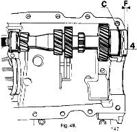
The general appearance of the Type 352 Gearbox is as seen in Fig. 1., with an identification tag as shown.
F.2 - GEAR LINKAGE - Section Menu
- The gear lever must be vertical.
- The centre pivot assembly must be between 88� and 92� to centre line of car.
- The universal joint on the gearbox must be set in neutral, positioned opposite the 1st and 2nd gears.
)
The gears are selected by moving the gear lever to the positions shown in Fig. 2.
)
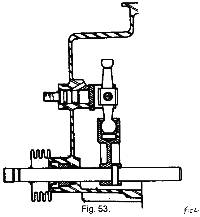
The linkage between the gear lever and the gearbox is basically as shown in Fig.3.
To Detach Linkage From Gearbox.
-
Select 4th gear.
)
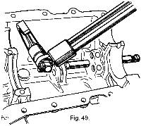
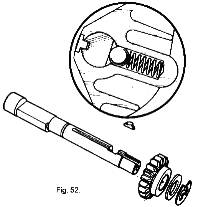
Knock out the pin, which holds the universal joint on the rear longitudinal link to the gearbox selector shaft. See Fig. 4.
Pull the linkage from the selector shaft. Replace in the reverse order.
To Remove Complete Linkage.
-
Detach rear longitudinal link, as detailed.
Remove the vertical pivot bolt from the bracket on the front of the clutch housing, freeing the universal joint assembly.
Remove the gear knob by unscrewing from gear lever, and remove the tunnel trim.
Remove the four bolts from the gear lever pivot mounting, allowing the gear lever with the spacer and pivot, to drop into the chassis centre section.
The complete gear linkage can now be withdrawn from the rear of the car.
Replace in reverse order. Ensure that the spacer is replaced above the gear lever pivot, in the chassis centre section.
F.3 - UNIVERSAL JOINT ASSEMBLY - Section Menu
)
The central universal joint assembly is as shown in Fig. 5.
To dismantle
-
Knock out pins from front and rear link tubes.
(Remove pivot bolt from pivot bracket, on clutch housing when dismantling on car.)
Heat the ends of each link tube sufficiently to unlock the 'Loctite', and turn the complete assembly in an anti-clockwise direction, (looking from the rear,) until detached from the link tubes.
The front tube is threaded right hand, and the rear is left hand. The spherical joint is 'Loctited' to the universal joint, and has to be heated to be removed.
Slacken the locknut and unscrew the spherical joint from the pivot.
Remove the spacing bushes from top and bottom of the pivot rubber bush.
Remove the bush.
NOTE: During re-assembly of the gear change linkage it is important that, where specified, LOCTITE High Strength Retaining Compound Type 35 must be used as follows:
Thoroughly clean and degrease the mating faces.
Spray the mating faces with 'Locquic' primer, Grade 'T' and allow to dry completely.
Apply Loctite Type 35 liberally over the mating faces and assemble the components as described.
The completed assemblies must be left to cure for a minimum period of 6 hours.
REASSEMBLY.
-
Replace rubber bush into pivot, screw spherical bearing, with locknut into pivot, to the dimension given in Fig. 5., and tighten the locknut.
Fit the spherical joint with 'Loctite', to the front pin, (longer and R.H. thread) of the universal joint, so that the grease nipple is underneath.
Clamp the joint onto the shank of the universal joint, by washers and a �" U.N.F. nut, until the 'Loctite' has cured.
When cured remove the �" nut and washers.
Refit gear lever assembly, front and rear longitudinal link tubes, and the pivot bracket assembly to the car, in reverse order to removal instructions.
Apply 'Loctite' to both threads of the universal joint, and screw the complete joint assembly into both tubes, turning clockwise. If both tubes and the universal joint are being used again, align the holes and fit new 1/8" X 1" long pins. Allow the 'Loctite to cure.
If new components are being used, the coupling assembly must be screwed into the tubes to the position, (with the pivot pin in place) where the following conditions apply:
F.4 - REVERSE INDENT MECHANISM - Section Menu
)
To Remove
-
Remove the cover. A.
Remove the Nyloc nut and knock out the pin from the cam. B.
Hold the ball in place against the spring pressure and remove the cam, ball and spring, and spacing washer if fitted.
Remove the indent housing from the rear cross member. C.
Replace in reverse order, 'Loctiting' and pinning the cam to the shaft, and liberally smearing the spring and ball with molybdinum disulphide grease.
SETTING REVERSE INDENT.
-
If either the cam, or the gearbox shaft, need renewing at any time, the cam must be set as follows:
-
Assemble the indent housing into the rear cross member and put the ball and spring into place.
Put the cam onto the shaft with 'Loctlte', fit the Nyloc nut and tighten lightly.
Select first gear. Take up free play in system by lightly holding lever over to right hand side.
Adjust cam so that the ramp has just come into contact with the ball. Fully tighten nut.
Use the pilot hole in cam as location to drill through shaft, and fit one eighth inch pin.
Fit cover.
F.5 - REMOVING AND REFITTING THE GEARBOX - Section Menu
Place protective coverings on the body sides around the engine compartment.
Removal of the gearbox is facilitated if the engine compartment lid is detached.
Remove the two nuts and penny washers under each hinge.
Remove the luggage box.
-
- Disconnect the leads to the alternator, slacken the belt, and remove the alternator.
- Drain the gearbox, using tool (Part No. X046 E 6167Z).
- Disconnect the speedometer drive cable at the gearbox rear housing.
- Disconnect the leads to the reversing lamp switch.
Remove the nave plates (hub caps [JJ]) from the rear road wheels, and slightly slacken the nuts.
Chock the front road wheels.
Raise the rear of the car and place a stand beneath each side of the chassis at the rear.
Remove the rear road wheels.
Disconnect the clutch cable from the lever at the bell housing.
Remove the silencer (muffler) assembly.
Remove the bolts securing the silencer (muffler) mounting bracket to the gearbox.
Unscrew the bolts retaining the lower suspension links to the gearbox bracket, allowing the links to drop clear.
)
Drive the roll pins from the inner universal joints on the transmission shafts by means of a drift (Part No. X046F6171Z) (Fig. 7.)
Free the drive shafts from the gearbox output shafts by withdrawing them outwards from their splines noting the spacers and shims fitted on the output shafts.
Remove the starter motor.
Place a jack under the rear of the gearbox.
Remove the reverse indent cover.
Remove the two bolts from the rear cross member, lower the gearbox, and remove the jack.
Remove the bolts from the clutch housing, and pull the gearbox rearwards until clear of the clutch shaft.
REFITTING
-
Carry out the removing operations in reverse, paying attention to the following points:
-
Lightly grease the splines on the clutch shaft.
Grease the output shaft splines with a graphited grease.
Place the pin holes at the bottom of one of the splines in the transmission shaft, in line with the smaller hole on top of the output shaft splines. Note that there are two holes in the output shaft, one slightly larger than the other.
)
To make it easier to fit the transmission shaft roll pins, use the cranked end of drift. (Part No. X046F 6171Z).
F.6 - OVERHAULING THE GEARBOX - Section Menu
)
Dismantling
-
Secure the gearbox to bracket (Tool No. X046F 6176Z) which is fitted to either the adjustable stand, (Tool No. X046E 6365Z) or the bench stand.
Remove the securing bolts from inside the clutch housing and pull off the housing, complete with the clutch operating shaft.
Remove the reverse indent mechanism
Remove the cross member.
Remove the rear housing securing bolts and remove the component.
)
Remove the locking plates from the large differential bearing adjusting nuts and unscrew the nuts by means of Special Tool (Part No.X046 F 6179Z).
Remove the bolts, which clamp the two halves of the gearbox housing together.
)
Remove the suspension bracket, and separate the half housing.
Push out the differential bearing outer race from each half housing by means of a suitable tube. Remove the spacer and the adjusting shims from the primary shaft bearings. Remove the differential.
Remove the secondary gear cluster and the stud, which locks the outer track ring on the double roller bearing.
Remove the primary shaft.
Gearshift Control.
)
Tap out the roll pin from the fork by means of drift. (Part No. A046F 6180Z).
Remove the shaft, fork, locking ball and spring.
Remove the locking disc shown arrowed, from between the two shafts.
Engage first gear.
Pull back the reverse shaft as far as possible towards the rear end.
)
Tap out the roll pin from the 1st- 2nd shaft fork using drift.
Remove the shaft, fork, locking ball and spring.
)
Remove the reverse selector by unscrewing the bolt, and remove the shaft.
)
Remove retaining circlip and take out the shaft, gear wheel, friction washer, guide, locking ball, and spring.
)
Separate the clutch shaft from the primary shaft by pushing out the roll pin by means of drift. (Part No. A046F 6171Z).
)
Extract the bearing from the differential end by means of extractor, (Part No.X046F 6168Z) fitted with shell, (Part No. X046F 6172Z).
)
Extract the second bearing by means of the same extractor fitted with shell, (Part No.X046F 6173Z).
Secondary Shaft.
-
NOTE: Before dismantling the 1st- 2nd speed synchronizer hub an electric oven capable of achieving a temperature of 250�C (482�F) is necessary for reassembling.
Grip the shaft in a fibre faced vice on the first speed gear wheel. Engage 1st gear.
)
Unlock the speedometer drive worm and unscrew it by means of spanner, (Part No.X046F 6175Z).
Remove :
-
- the double taper roller bearing.
- the pinion depth adjusting washer.
- the 4th speed gear wheel and its ring.
)
Remove the 3rd- 4th synchronizer hub by means of special tool, (Part No. X046F 6181Z) and a press.
)
Remove the gear wheel stop washer retaining key, shown arrowed, the 3rd speed wheel gear stop washer, the 3rd speed gear wheel and its ring, the 2nd speed gear wheel stop washer and the 2nd speed gear wheel and its ring.
Mark the position of the 1st- 2nd speed synchronizer sliding gear wheel relative to its hub, remove the gear and the hub stop washers.
)
Remove the 1st- 2nd speed synchronizer hub by means of the special tool and the press.
Remove the 1st speed synchronizer, the 1st speed gear wheel stop washer, and the 1st speed gear wheel.
)
Fit the guard over the pinion bearing to retain the outer race, and the rollers in position. NOTE: that the inner race cannot be replaced.
F.7 - DIFFERENTIAL - Section Menu
On the crown wheel side, remove two diametrically opposite securing bolts.
Remove the bearings by means of tool (No.X046F6169Z) fitted with claws (Part No. X046F 6174).
Remove the remaining crown wheel securing bolts.
These are self locking bolts which cannot be used again.
Push out the planet wheel shaft roll pin by means of drift (Part No. X046F 6171Z).
Separate the various parts.
F.8 - REAR HOUSING - Section Menu
Unscrew the bolt securing the speedometer drive assembly.
Pull out the assembly, together with the 'O' ring.
Remove the rubber bellows from the selector shaft.
Pull out the selector shaft, and remove the seal.
)
Pull out the selector swivel assembly, and remove the 'O' ring.
CLEANING AND CHECKING
-
Clean and check all the parts.
All seals and gaskets, roll pins and self locking bolts must be replaced by new ones.
F.9 - REASSEMBLING - Section Menu
- Crown Wheel and Pinion.
The final drive pinion and crown wheel are lapped together during manufacture, and have to be replaced as a unit, complete with the roller bearing, which cannot be supplied separately.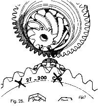
A common marking is inscribed on both the crown-wheel and the pinion, for example 27:200. OTHER MARKINGS MUST BE IGNORED. - Matching Final Drive Pinion Shaft To Synchronizer Hub.
If the synchronizers can be used again, the size of the new final drive pinion to be ordered must be determined in order to ensure that the synchronizer hubs match the final drive pinion shaft.
To do this, measure the old final drive pinion.
If the synchronizers are damaged and the final drive pinion can be used again, the size of the synchronizer hubs to be ordered must be determined in order to ensure that they match the final drive pinion.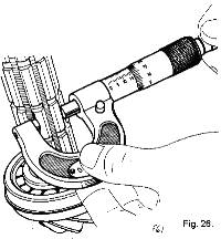
To do this, measure the final drive pinion, as follows.-
Measure the dimension across 2 of the splines on the final drive pinion shaft by means of a micrometer.
Take a number of measurements at different points around the splines at the point where the synchronizer hub fits and find the average.
There are 2 different size groups for the final drive pinion shaft and the synchronizer hubs.
They can be identified by a colour code paint mark.Final Drive Pinion Shaft Dimension Colour Code 16.61 to 16.63mm (.6539 to .6547") Blue 16.64 to 16.66 mm (.6551 to .6559") Yellow The synchronizer hubs are fitted to the final drive pinion shaft on the press:
-
1st- 2nd speed hub: hot at a temperature of 250�C (482�F).
3rd- 4th speed hub: cold.The 1st- 2nd speed synchronizer.
As the sliding gear wheel and the hub are matched, mark before separating them.
The position mark should be made on the 2nd speed gear wheel side, (the same side as the chamfered) on the sliding gear wheel so that it can be seen after the hub has been fitted.Place the hub in an electric oven and heat it to 250�C (482�F).
Wait until it has reached full temperature before starting to re-assemble the secondary shaft assembly.The 3rd- 4th speed synchronizer.
-
It is not necessary to dismantle this.
If it has been dismantled and can be used again re-assemble it as follows:-
Place the three keys and the two springs on the hub (as shown).
Place the sliding gear wheel in the correct position, with the groove in the sliding gear wheel on the opposite side to the two notches in the hub, and the reference mark on the sliding gear wheel in line with the mark made on the hub during dismantling.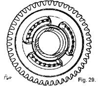
Place the synchronizer spring on the 1st speed gear wheel so that it covers the 3 notches.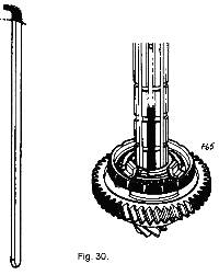
Place the following on the final drive pinion (already fitted with its bearing)
- the 1st speed gear wheel and its ring.
- the 1st speed gear wheel stop washer.
Turn it, and locate it by means of a dummy key (this is a washer retaining key one lug of which has been removed).
The dummy key is to be placed in one of the keyways, which has an oil hole in it.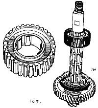
Take the 1st- 2nd speed gear wheel hub from the oven and place it on the final drive pinion in the correct position; the part with the position mark on it for positioning the sliding gear wheel is to face towards the 2nd speed gear wheel; the unsplined portion is to be in line with the dummy key.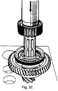
Push on the hub on the press until it makes contact with the stop washer.
Hold the synchronizer ring in a central position, with the lugs below the level of the stop washer so as not to damage the spring.
Hold pressure on the press for a time in order to allow the hub to cool down (Assist by cooling with compressed air).
Release pressure.
Remove the dummy key.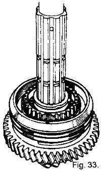
Fit the 1st- 2nd speed sliding gear wheel:
- with a chamfer on the 2nd speed gear wheel side.
- with the position reference in line with that on the hub.
Fit the hub stop washer (turn it to align its spline with those on the final drive pinion).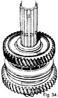
Place the synchronizer spring on the 2nd speed gear wheel in the position as on the 1st speed gear wheel. Position the 2nd speed gear wheel and its ring. Position the gear wheel stop washer (turn it to align its splines with those on the final drive pinion shaft).
Fit the 3rd speed wheel gear and its ring.
Position the stop washer so that its splines align with those of the final drive pinion shaft, and fit the gear wheel stop washer retaining key into one of the keyways that has an oil hole in it. Fit the 3rd- 4th speed synchronizer, with the notches on the hub on the 3rd speed wheel side, and in line with the retaining key.
Press into place until it makes contact with the 3rd speed gear wheel stop washers.
Warning.
Ensure that the 3 notches on the synchronizer hub are in line with the 3 keys.Fit
- the 4th speed gear wheel and its ring.
- the pinion depth adjusting washer (that was removed during dismantling).
- the double taper roller bearing and the speedometer drive worm gear.
Grip the shaft in a vice, across the 1st speed gear wheel.
Engage 1st gear.
Tighten the speedometer drive worm gear by means of torque wrench (Part No.X046F 6353Z) fitted with spanner (Part No. X046F 6175Z): 10 to 12 m. da N. (75 to 85 lb/ft).
Do not lock it, so that the pinion depth can be adjusted later.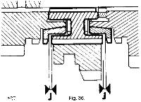
Check that the space at J between the synchromesh hub and each synchromesh ring is 0.20 mm. (.008").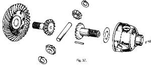
Fit the following in the differential housing: [1]-
- The bakelite impregnated washer (with the lubrication groove on the sun wheel side).
- The 1.97 to 2 mm. (.077 - .079 in.) shim (Use the thicker shim 2.03 to 2.07 mm (.080 - .082 in.) only when the play between the planet and sun wheels is excessive).
- One sun wheel (dipped in oil grade EP 80).
- The planet wheels and their friction washers. (Place the locating lug in the hole in the housing.)
Insert the planet wheel shaft (align the hole in the shaft with that in the housing) and fit the roll pin.
Dip the second sun wheel in oil grade EP 80 and fit it in the crown wheel.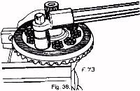
Fasten the crown wheel to the housing by means of new self locking bolts (Part No. X046F 6139Z).
Tighten the bolts to a torque of 6 m. da N. (45 lb/ft.) using torque wrench (Part No. X046E 6353Z) for the 10 mm. (.394") diameter bolts.
Use a press to fit the bearings to the following:TRANSMISSION ASSEMBLY
Adjusting Pinion Depth
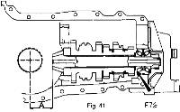
The final drive pinion must be positioned by means of the washer shown arrowed, so that the distance from the front face to the crown wheel centre line at 'A' is 59 mm. (2.323 in).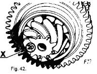
NOTE In some cases the depth 'A' may increase by the amount marked on the pinion at 'X', which is given in hundredths of a millimetre.
The example shown in Fig. 41.is +0.20 mm., which has to be added to 59 mm. to give 59.20 mm (2.323 + .008 = 2.331 mm).Checking the Pinion Depth
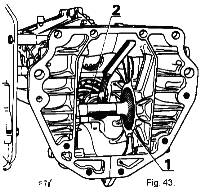
This operation is carried out with mandrel (1) (Part No. A074F 6020Z) which provides the crown wheel centre, and spacer (2) (Part No. A074F 6021 Z) which rests against the front face of the final drive pinion.Fit the secondary shaft to the left half of the housing.
Fit the right hand half-housing and secure it in place by a number of bolts. (Do not tighten them.)
Temporarily fit the front housing to hold the double taper roller bearing track ring in position. Tighten the half-housing securing bolts.
Fit mandrel (1). (see Fig.43.)
Fit spacer (2) against the front face of the final drive pinion.
Measure by means of a set of feeler gauges, the gap between the spacer and the mandrel.
This must be 0.50 mm.(.020 in.)
If necessary adjust by means of the washer.
Washers are obtainable in thicknesses of 3.50 mm. to 4.10 mm. (.138 to .162") increasing in increments of 5/100 mm. (.002").
When the final adjustment has been obtained, remove gauge.
Remove the secondary assembly and lock the speedometer drive worm.Adjusting the differential bearings:
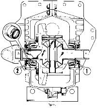
The adjustment is obtained by screwing nuts (1) and (2) in or out. (see Fig.44.)Fit the bearing outer race to each half housing so that it is slightly below the inner face of the housing.
Fit the differential, together with its bearings, into the right -hand half housing.
Fit the half-housing together, replace bolts, and tighten with a torque spanner in the order shown in Fig. 54., to 2 m da N (15 lb/ft.) for 7 mm. bolts and 2.8 m.da N (20 lb/ft.) for 8 mm. bolts.
Smear the threads on the nuts and in the housing with 'Loctite AV' locking compound. Screw the adjusting nut into each half-housing until it makes contact with the bearing track ring, using wrench (Part No. X046 F 6179Z) (see Fig.10..)
If the original bearings are being are being used again, the differential must turn without play.
Continue to screw in the nuts, which push in the bearing track rings.
Take care to screw in nut 2 (Fig.44.) on the differential housing side a little more than the one on the other side in order to obtain a crown wheel and pinion back lash which is slightly larger than that required on final assembly.
When the differential can be felt to be turning without play, stop screwing in the nuts.
This is the final adjustment.
Mark the position of the nuts with reference to the housing (by means of punch mark).
Remove the left-hand housing and the differential.
If new bearings are fitted the differential should rotate with a resistance torque of between 0.050 and 0.150 m da N.
Screw in nut (2) on the differential housing side more than the nut on the other side to obtain a back lash higher than the required figure on the final assembly.
When the differential becomes slightly stiff to rotate, check the preload as follows:Adjusting the bearings.
Turn the differential a number of times to centralize the bearings.
Wrap a string around the differential housing.
Pull on the string with a spring balance.
The differential should rotate under a load of between 1 and 3 da N (2 to7 lb.).
If the adjustment is not correct, screw the nut on the differential housing side slightly in and check the preload again.
When the correct adjustment has been obtained, mark the position of the nuts with reference to the housing.Adjusting the primary shaft bearings.
Positioning the primary shaft.
-
Fit into the right-hand half housing the primary shaft, and the secondary shaft assembly.
The face(A) on the primary 3rd speed gear wheel should be offset to face (C) on the secondary shaft 3rd speed gear wheel by the same amount as face (B) on the primary shaft 4th speed gear wheel is offset to face (D) on the secondary shaft assembly 4th speed gear wheel.
This position is adjusted by means of washer (1 ):
Washers are available in thicknesses of: 2.50-2.75-3 -3.25 -3.50-3.75 and 4 mm. (.079-.089-.108-.118-.128-.138-.148 -.158 in).
When the correct adjustment has been obtained, remove the secondary shaft assembly.Adjusting the bearings.
-
With the primary shaft in position, place the left half-housing in position without securing it.
Fit the adjusting shim (C) and the spacer (4).
The shaft should turn freely, without play, and the spacer should project above the housing by .20mm (.008 in.), the thickness of the paper gasket on the front housing.
Place a rule against the spacer and check the dimension (F) between the rule and the housing by means of a set of feeler gauges.
If the adjustment is not correct, increase or reduce the thickness of the shim pack C:
Shims are available in thicknesses of: 0.10 - 0.20 - 0.25 - 0.50 and 1 mm. (.004 -.008 - .010- .020 - .040 in.)
When the adjustment is complete, remove the right hand half housing and the primary shaft.
Assemble the clutch shaft to the primary shaft by securing the roll pin.
IMPORTANT - Roll Pin fitting:
When reassembling, fit the roll pins as shown in Fig.71.
Their slots MUST always face towards the speedometer drive housing.REASSEMBLING
Gear Shift Control.
-
Engage the reverse shaft.
Fit the reverse swivel lever, engaging its end into its slot in the reverse shaft.
Tighten its pivot to a torque of 2.8m.da.N (20 lb/ft.) by means of torque wrench (Part No.46E 6353)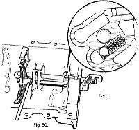
Fit the 1st - 2nd selector shaft locking ball and spring. Insert the 1st - 2nd selector shaft. Fit the 1st - 2nd selector fork (with the hub towards the control end) and pin it in place.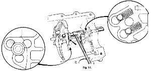
Fit the locking disc between the shafts.
Fit the 3rd - 4th selector shaft locking ball and spring. Insert the shaft and fit the selector fork (with the hub towards the differential end) and pin it in place.Reverse shaft and gear.
Fit the following onto the left hand half housing:
the locking ball and spring.
Engage the shaft and fit the gear wheel (with the hub towards the differential end) followed by the friction washer (with the bronze face towards the gear wheel).
Insert the guide from inside the bore and push the shaft fully in.
Fit the gear wheel retaining circlips.Rear Housing.
Fit a new oil seal in the housing, replace the selector shaft, and fit new rubber bellows.
Fit a new 'O' ring to the shaft of the selector swivel assembly, and replace into rear housing.
Replace the speedometer drive assembly, using a new 'O' ring, and fit its securing bolt.
Fit the following to the right-hand half housing:
- the primary shaft.
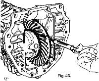
- the secondary shaft assembly,
- the differential. (see Fig. 11.)
Smear the half housing assembly faces with 'Hylomar' jointing compound.
Fit the left-hand half housing to the right-hand assembly.
Make sure that the end of the reverse swivel lever is in the slot of the reverse gear wheel shaft.
Insert the half housing securing bolts, but do not tighten them.
Fit bracket.
Fit the primary shaft bearing adjusting shims and the spacer.
Use jointing compound on a new paper gasket, offer up the rear housing, and engage the selector swivel with the slots in the selector shafts.
Replace the bolts but do not tighten.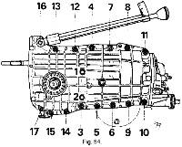
Tighten the half housing assembly bolts in the order shown on the illustration:
7 mm bolts: 2 m. da N (15 lb/ft).
8 mm bolts: 2.8 m. da N (20 lb/ft).
Finally tighten the rear housing securing bolts.
Secondary Shaft.
)
)
)
)
)
)
)
)
)
)
)
)
)
)
)
)
)
)
)
)
)
)
)
)
)
)
)
)
)
)
F.10 - ADJUSTING THE CROWN WHEEL AND PINION BACKLASH - Section Menu
The backlash is obtained by screwing nut (2) on the differential housing side in or out and screwing nut (l) on the opposite side in or out by the same amount. (See Fig. 44.)
Feel the backlash by hand.
If it is clearly too large unscrew nut (2) on the differential housing side and screw in nut (1) on the crown wheel side to obtain a smaller backlash.
)
Mount a dial indicator on the housing with its plunger square with the flank of one of the crown wheel teeth.
The backlash should be between 0.12 and 0.25 mm (.005 to .010 in.).
If it is excessive, unscrew nut (2) on the differential housing side and screw in nut (1) on the crown wheel side by the same amount.
If there is insufficient backlash, unscrew nut (1) on the crown wheel side and screw in nut (2) on the differential housing side by the same amount.
)
When the correct back lash has been obtained, lock the nuts by means of the locking plates.
F.11 - TYPE 365 GEARBOX - Section Menu
The Type 365 Gearbox was introduced into current Production as an optional extra on Europa Special at Chassis No.
-
72081783P - U.K.
72081101Q - Export
72082684R - North America
GEARBOX IDENTIFICATION
)
The general appearance of the Type 365 gearbox, together with its identification tag, is shown in Fig. 57.
F.12 - GEARSHIFT - Section Menu
)
First and second gears are selected by moving the lever to the left until resistance is felt, and engaged by moving it forwards for first gear and rearwards for second gear.
Third and fourth gears are selected by moving the lever to the right, through neutral position until resistance is felt, then forwards for third and rearwards for fourth gears.
Overdrive (fifth) gear is selected by moving the lever fully to the right in neutral, against spring pressure and forwards into gear.
Reverse gear is selected by moving the lever fully to the left in neutral, against spring pressure and rearwards into gear.
)
)
)
)
GEAR LINKAGE
The gear linkage fitted to cars equipped with the Type 365 gearbox, is identical to the linkage described on Pages 3 to 5 inclusive of this Section, with the exception of the lengths of the longitudinal links (see Service Parts List).
F.13 - REVERSE INDENT MECHANISM - Section Menu
Removal, replacement and setting of the reverse indent mechanism will be found on Page 6 of this Section.
It should be noted, however, that the indent mechanism used on the Type 365 gearbox is NOT interchangeable with the indent mechanism used on the previous Type 352 gearbox (see Service Parts List).
F.14 - REMOVING AND REFITTING THE GEARBOX - Section Menu
The Information published on Pages 7 and 8 of this Section is satisfactory for this gearbox.
F.15 - OVERHAULING THE GEARBOX - Section Menu
- Return the 3rd - 4th speed selector to neutral.
- Remove the 5th speed selector shaft.
- Remove the locking ball between the 3rd - 4th and 5th speed selector shafts.
- Push out the roll pin from the 3rd - 4th speed selector fork using the drift. (Part N o. X046 F 6180Z)
- Remove the shaft, fork, locking ball and spring. Remove the locking disc (see Fig. 12.) from between the shafts.
- Remove the reverse gear selector and reverse gear shaft.
- Using drift (Part No. X046 F 6180Z), push the roll pin from the 1st � 2nd speed selector fork.
- Remove the selector shaft and fork, together with locking ball and spring.
Remove the primary shaft as detailed on Pages 11 and 12 of this Section. - Grip the shaft assembly in a fibre-faced vice, holding it by the 1st speed gear.
- Remove the double taper roller bearing, pinion depth adjusting washer, the 4th speed gear and its ring.
- Mark the position of the sliding gear in relation to its hub, then remove the 3rd - 4th speed synchro sliding gear with its retaining keys.
- Fit the 4th speed gear and its ring.
- Fit the pinion depth adjusting washer (removed during dismantling.).
- Fit the double taper roller bearing.
- Fit the spacer plate; this is necessary to obtain correct adjustment of pinion depth.
- Fit the5th, speed gear, wavy washer and speedometer drive worm.
- Tighten the speedometer drive worm, and check clearance between 3rd and 4th speed synchro rings and their relative hubs, as shown on Page 19.
As the Type 365 gearbox is very similar to the Type 352 gearbox, with the exception of the overdrive (fifth) gear, only the differences in procedure will be described here.
For all other dismantling, overhauling and rebuilding procedures, see Pages 9 to 28 inclusive of this Section.
DISMANTLING.
)
Secure the gearbox to bracket (Tool No. X046 F 6176Z) which is fitted to either the adjustable stand, or the bench stand.
Release the retaining bolts and remove the clutch housing, complete with clutch shaft.
Remove reverse indent mechanism and cross member.
Select 4th speed then remove plug, spring and 5th speed detent plunger.
Release the retaining bolts and remove rear cover.
Return the selector forks to neutral and select both 5th and reverse speeds together.
)
Loosen the 5th speed synchro hub nut.
Loosen the speedometer drive worm nut using Special Tool (Part No. X046F 6175Z).
Return the selector forks to neutral, then select 4th speed.
)
Push out the 5th speed fork roll pin (see Fig.65) using the drift (Part No. X046 F 6180Z).
Mark the 5th speed sliding gear and hub in relation to each other.
Remove the 5th speed hub and synchro assembly and fork after removing the retaining nut.
Remove the 5th speed gears after removal of the speedometer drive worm nut.
)
Remove bolts retaining spacer plate (arrowed in Fig. 66), and pull off plate.
Carry on with parting the two halves of the gearbox as detailed on Page 9.
After parting the two halves of the gearbox casing, and the removal of the differential, secondary gear cluster and primary shaft, it is necessary to remove the gearshift control.
)
The secondary shaft is dismantled as follows (see Fig. 67):
The remainder of the dismantling procedure will be found on Pages 13 and 14.
Reassembly of the gearbox is as on Pages 15 to 19 inclusive, with the exception that the 4th and 5th speed gears are fitted to the secondary shaft as follows.
)
F.16 - DIFFERENTIAL - Section Menu
- The bakelite impregnated washer, with the oil groove facing the sun wheel.
- The 1.97 � 2 mm. (.077 - .079 in.) shim; use the thicker shim 2.03 - 2.07 mm. (.080 - .082 in.) only when the free play between the planet and sun wheels is excessive.
- One of the sun wheels, having first dipped it in EP .80 oil.
- The planet wheels (1 and 2) (see Fig. 69) and their thrust washers, ensuring the locking tags are located in the holes in the housing.
- Insert the planet wheel shafts such that they do NOT protrude beyond the planet wheels.
- Repeat operations 'd' and 'e' for the planet wheels. (3 and 4).
- Insert the hub (5), noting that its chamfered ends must face towards the two small shafts. Push all three shafts in as far as possible, lining up the holes with those in the housing. Secure the small shafts with new roll pins.
- Dip the second sun wheel into an EP.80 oil and insert into crown wheel. Assemble the crown wheel to the differential housing by means of new, self-locking bolts, noting that the bolt with the 'pip' locks the larger planet wheel shaft. Tighten the bolts to a torque loading of 65 - 80 lbs.ft. (9 to 11 m.da N). Fit the 'O' ring seals in position on the sun wheels. Note that after assembly, the differential may be stiff to turn.
- Fit the bearings to the differential assembly as given on Page 21.
- Fit the primary shaft positioning washer.
- Fit the double taper roller bearing.
- Using a press, fit the roller bearing inner track to the shaft.
- Using a suitable grease, insert the bearing rollers into the outer track ring, then slide primary shaft through this assembly, retaining the whole with its circlip.
- Fit the clutch shaft to the primary shaft using a new roll pin for its retention.
- The three keys.
- The two springs.
- The sliding gear, aligning the marks made during dismantling.
)
Fit into the differential housing:
Primary Shaft.
5th Speed Synchro
-
Note that the hub and its sliding gear are a matched set.
)
Using Fig. 70. as a reference, fit on to the hub:
F.17 - TRANSMISSION ASSEMBLY - Section Menu
- Speedometer worm nut.
- Wavy washer.
- 5th speed gear.
- Spacer plate.
- Fit the felt washer (A of Fig. 74) behind the bush.
- Assemble the rocking lever to its pivot pin, and insert into cover.
- Fit the selector finger and control shaft.
- Secure the control shaft with its washer and nut.
- Fit the speedometer driven gear, together with its guide and new 'O' ring seal.
- The primary shaft.
- Select 4th speed, then fit the secondary shaft.
Insert the stop peg for the outer track ring of the double taper roller bearing. - The differential (see Fig. 11.)
- Spacing washer.
- Needle roller bearing and sleeve.
- 5th speed driven gear with its synchro hub, sliding gear and fork assembly.
- The wavy washer and synchro nut.
- 5th speed gear.
- Wavy washer and speedometer worm nut.
- Primary shaft nut to 45 lbs. ft. (6 m.da N).
- The speedometer worm nut to 75/85 lbs. ft. (10/12 m.da N).
Lock the two nuts.
Adjusting Pinion Depth.
-
Adjusting the pinion depth for the Type 365 gearbox is as given for the Type 352 gearbox on Page 21.
Checking the pinion depth is the same as given on Page 22, with the exception that before bringing the two halves of the casing together, it will be necessary to remove the spacer plate, refitting it after bolting the casing together.
When the final adjustment has been obtained, remove the checking gauge, rear cover, left-hand half casing and secondary shaft assembly.
Primary Shaft Position.
-
This is given on Page 24 with the exception that, before fitting the secondary shaft assembly into the right-hand half casing, it will be necessary to remove the:
The primary shaft is positioned by means of a washer ('1' of Fig. 47.), the washers being varying thicknesses to accommodate correct positioning (see Page 24).
Note that the stop ('R' of Fig. 47.) must be equal for both sets of gears.
When the correct adjustment has been obtained, remove both the secondary and primary shaft assemblies.
REASSEMBLING.
Selector Mechanism
-
IMPORTANT: Roll Pin fitting:
)
When reassembling, fit the roll pins as shown in Fig. 71.
Their slots MUST always face towards the speedometer drive housing.
Note that this instruction applies to both the Type 365 gearbox and the Type 352 gearbox.
Gear Shift Control.
-
Fit the reverse selector, reverse shaft, 1st - 2nd selector shaft and 3rd - 4th selector shaft as detailed on Page 26.
)
Fit the 5th speed selector shaft locking ball in position, and slide in shaft (see Fig. 72.)
)
Select 4th gear and retain in this position until gearbox is assembled.
Fit reverse shaft and gear as detailed on Page 27.
Rear Cover.
)
Fit the following to the right-hand half housing:
Smear the half-housings joint faces with 'Hylomar' jointing compound.
Fit the left-hand half housing, ensuring that the end of the reverse gear selector is correctly inserted in the slot in the reverse gear wheel shaft.
Fit the half-housing securing bolts, but do not tighten them at this stage.
)
Fit the spacer plate (Fig. 75) after applying 'Hylomar' to its gasket.
Replace the locating dowels. Fit and tighten, the three securing bolts.
)
Tighten the half-housing securing bolts in the sequence shown in Fig. 76.
-
7 mm. bolts to 15 lbs. ft. (2 m.da.N).
8 mm. bolts to 20 lbs. ft. (2.8m.da.N).
Primary Shaft.
-
Assemble the following on to the primary shaft:
Secondary Shaft.
-
Assemble the following on to the secondary shaft:
Secure the 5th speed selector fork with a new roll pin.
Return the selector forks to the neutral position (from 4th)
Select 5th speed and reverse together.
)
)
Check the clearance 'J' (Fig. 78) between the 5th speed synchro ring and the hub rim.
A minimum clearance of .008 in. (.20 mm.) is required, with the gear hard against the hub, and the synchro ring in line with the gear cone.
Return the selector forks to neutral, then select 4th speed.
Fit the rear cover after applying 'Hylomar' to its gasket.
)
Ensure the end of the rocking lever enters the slot in the 3rd - 4th speed selector shaft. (Fig. 79.)
Push the cover on and fully tighten the securing bolts.
)
Fit the 5th. speed selector locking ball and spring (Fig. 80.)
Smear the plug threads with Loctite "AV", fit washer and screw in plug.
)
Fit the 5th speed detent spring and plunger. Smear the plug threads with Loctite "AV". Fit the washer and screw in the plug.
Return the selector forks to neutral.
Remove gearbox from the stand.
F.18 - TYPE 336 GEARBOX - Section Menu
The Type 336 Gearbox was used from the introduction of the Europa Twin Cam until the Type 352 Gearbox was introduced. With the exception of the gear change linkage, described and illustrated here, the information printed in Section 'F' of the Europa Workshop Manual is relevant and should be referred to.
GEARBOX IDENTIFICATION.
)
The general appearance of the Type 336 Gearbox is as seen in Fig. 1. with an identification tag as shown.
F.19 - GEAR LINKAGE - Section Menu
)
The gears are selected by moving the gear lever to the positions shown in Fig. 2.
)
The linkage between the gear lever and the gearbox is as shown in Fig. 3.
The dimensions shown between centres of the ball joints on the relay lever and the link tube must be strictly adhered to during the initial setting up of the linkage.
To Detach Linkage From Gearbox.
-
Remove the bolt, the two washers, and the two rubber bushes, which hold the location link 'G' to the gearbox central web.
Remove the Nylon nut, the bolt, and the two spacing washers, which hold the rearmost ball joint to the actuator 'H'.
Replace in the reverse order. Ensure that a metal washer and rubber bush are either side of the gearbox web before screwing bolt into location link 'G', and that a spacing washer is fitted to either side of the ball joint on refitting the bolt and Nyloc nut.
GEAR LEVER ADJUSTMENT.
)
Following replacement of the linkage to the gearbox it may be necessary to adjust the gear lever to the vertical position.
This may be done as shown in Fig. 4. by screwing the rearmost ball joint in or out of the rear tube at 'B' to adjust the fore and aft position of the gear lever, and adjusting the lateral position of the lever by means of the ball joint in the location link at 'A'.
REAR TUBE CLEARANCE.
)
In certain circumstances the rear longitudinal link may clash with the exhaust system when in 1st and 2nd gear position.
The clearance at the closest point should be adjusted as shown in Fig. 5. to 4.8 mm (0.19 in.) by screwing out the ball joints on the link tube at 'A' and 'B'.
Editors Notes:
-
[1] Added the word 'differential' for clarity. [JJ]
Other Notes: [edit]
This area is a public scratchpad for notes.
Please be courteous with what you post, and do not erase someone else's work.