M.1 - GENERAL DESCRIPTION - Section Menu
The electrical system is a 12-volt earth return type employing NEGATIVE earth polarity. The system incorporates a charging, lighting, starter, ignition and auxiliary circuits, operating through a fuse unit mounted on the right hand side of the backbone tunnel below the instrument panel. The charging circuit employs a 30 amp alternator with a separate electronic regulator.
A 57 amp/hour capacity battery is fitted on the right-hand side of the engine compartment, the negative earth lead of which is bolted directly to the chassis.
An inertia or pre- engaged starter motor is fitted on the left-hand side of the engine and engages with a ring gear on the engine flywheel.
Electric current is supplied to the starter motor by a solenoid switch mounted on the unit itself and is controlled by the ignition switch mounted on the instrument panel.
The ignition system consists of a distributor mounted on the right-hand side of the engine and driven by the camshaft, employing a centrifugal ignition advance control, a Ducellier ignition coil, and Marchal 34 HS sparking plugs, using suppression caps fitted to each high tension lead.
The two headlamps giving main and clipped beams incorporate the parking lamps. The combined dip and headlamp/flasher switch is mounted on the steering column nacelle.
Separate flasher lamps are mounted on the front of the car inboard of each headlamps assembly. At the rear combined rear stop and flasher lamps are fitted, the units also incorporating reflectors. Interior equipment includes electrically operated windows fitted as standard equipment and controlled by independent switches mounted on the instrument panel.
The facia instruments are mounted from the back of the panel, the fuel and temperature gauges being of the bi-metal type controlled by a 5 volt regulator mounted behind the panel. An oil pressure gauge electrically operated directly from the engine is fitted and an ammeter is also fitted together with a comprehensive set of warning lights.
Single or double two-speed windscreen wipers of the self-parking type are fitted, and electrically operated windscreen washers are included in the specification.
Description.
-
The battery features a 'clean-top' design with a one-piece manifold venting system. The terminals posts are the flat type drilled to accommodate the bolts passing through the cable connectors.
The battery is mounted in the boot (trunk) and held in position by a clamp. Batteries are supplied either filled and charged or 'dry-charged', that is with the cells in a charged condition and without electrolyte. Details of preparing 'dry-charged' batteries are given in later paragraphs.
Maintenance.
-
Battery maintenance consists mainly of regular inspection and servicing. Keep the battery and its surroundings clean and dry. Give particular attention to the top of the battery to prevent electrical leakage between the terminals.
Remove the manifold vent cover, and see that the vent holes are clear.
)
Check the electrolyte level and top up, when necessary. The correct level is just up to the perforated splashguard. Do not over-fill or acid will escape through the vent hales with detrimental effect to the connections and adjacent parts of the car.
The use of a Lucas Battery Filler (or similar) will be found helpful in this topping-up process, as it ensures that the correct electrolyte level is automatically obtained and also prevents distilled water from being spilled over the top of the battery.
Distilled water should always be used for topping-up. In an emergency, however, drinking water or clean rain water may be used. The following waters must not be used, salt water, chlorinated water, chemically softened water or stagnant water.
Never use a naked light when examining a battery, as the mixture of oxygen and hydrogen given off by the battery when on charge, and to a lesser extent when standing idle, can be dangerously explosive.
If a battery is found to need an excessive amount of topping-up, the cause should be sought. If an excessive charge is suspected, check the regulator setting. If one cell in particular is at fault, examine the container for cracks. NEVER transfer electrolyte from one cell to another.
When fitting the connectors to the battery, first smear the terminal posts with petroleum jelly or silicone grease.
Examine the earth connection to ensure that it is clean and free from rust or corrosion.
Specific gravity Test.
Measure the specific gravity of the electrolyte in each cell in turn, with a hydrometer. The reading given by each cell should be approximately the same; if one cell differs from the other by more than .040, an internal fault in the cell is indicated.
If the level of the electrolyte is so low that a hydrometer reading cannot be taken, the battery should be topped-up with distilled water and recharged. No attempt should be made to take a reading after adding the distilled water until the battery has been on charge for at least thirty minutes. NEVER transfer the electrolyte from one cell to another.
The appearance of the electrolyte drawn into the hydrometer when taking a reading gives a useful indication of the state of plates; if it is very dirty or contains small particles in suspension, it is possible that the plates are in a bad condition.
Check the specific gravity of the electrolyte (see Fig. 1) as an indication of the state of charge of the battery, using a hydrometer.
The specific gravity reading varies with the temperature of the acid electrolyte and it is customary to correct it to the corresponding value at a standard temperature of 15 C as follows: For each 10°C. above 15° C. add .007 to the reading.
For each l0°C. below 15° C. subtract .007 from the reading.
If the car is out of use for any length of time the battery should not be allowed to run down or to remain in a discharged condition. It should be recharged about every 2 weeks from an independent electrical supply.
Heavy Discharge Test.
No attempt should be made to carry out a heavy discharge test on this type of battery. The specific gravity test described in the foregoing paragraphs will provide a clear indication of the condition of the battery, provided the test has been carried out correctly. If any doubt remains, the battery should be checked by the nearest Exide agent.
Remember that if the battery is subjected to heavy loads (i.e. long periods of night parking with lights on) without suitable opportunities for recharging a low state of charge is only to be expected. A fault in the charging system or neglect during a period out of commission may also be responsible for any trouble.
Acid spillage or creepage can be neutralized by wiping the affected area with a fluffless cloth moistened with a dilute alkaline solution such as ammonia.
Recharging from an external supply.
-
If test indicate that the battery is discharged, but is otherwise in good condition, it should be re-charged either on the vehicle by a period of daytime running or on the bench from an external supply.
If the latter, the battery should be charged until the specific gravity and voltage show no increase over three successive hourly readings. During the charge the electrolyte must be kept level with the top of the separator guard by the addition of distilled water.
A battery in which all cells show a general failing off in efficiency will often respond to the process known as 'cycling'. This process consists of fully charging the battery as described earlier, and then discharging it by connecting to a lamp board, or other load, at the same rate.
Preparing New Batteries.
-
Batteries are normally supplied 'dry-charged' and before fitting to the car must be filled with acid as described under 'Filling the Cells'.
No initial charging is necessary, although, if time permits, a short freshening charge is advantageous.
Preparation of Electrolyte.
-
Electrolyte of the specific gravity stated in the following table is prepared by mixing distilled water and concentrated sulphuric acid, usually of 1.840 specific gravity.
The mixing must be carried out either in a lead-lined tank or in suitable glass or earthenware vessels.
Slowly add the acid to the water, stirring with a glass rod. Never add the water to the acid as the resulting chemical reaction causes violent and dangerous spurting of the concentrated acid.
The approximate proportions of acid and water are indicated in the following table:
-
Climates normally below 27°C. (80°F.):
-
Add one part (by volume) of acid of 1.840 specific gravity to 3.2 parts (by volume) of pure distilled water to obtain a final specific gravity of 1.260 at 15.5°C. acid temperature.
-
The specific gravities and their indications are as follows:
-
Climatic temperature of 15° C
Fully charged 1.280
25% discharged 1.240
50% discharged 1.200
75% discharged 1.160
Fully discharged 1.120 and below.
Climates normally above 27° C. (80° F.):
-
Add one part (by volume) of acid of 1.840 specific gravity to 4.3 parts (by volume) of pure distilled water to obtain a final specific gravity of 1.210 at 15.5° C. acid temperature.
Heat is produced by the mixture of acid and water, and the electrolyte should be allowed to cool before taking hydrometer readings - unless a thermometer is used to measure the actual temperature, and a correction applied to the reading as previously described - and before pouring the electrolyte into the battery.
Filling the Cells.
-
Whilst these batteries leave the factory in the fully 'dry-charged' condition, they may slowly lose some charge in storage. In view of this, the following filling instructions must be carefully observed:
-
With the acid, battery and room temperature between 15.5 - 37.7° C. remove the vent cover or plugs and fill (in one operation] each cell to the separator guard.
Measure the temperature and specific gravity of the electrolyte in each of the cells. Allow to stand for 20 minutes and then re-check the specific gravity and temperature of the electrolyte in each cell.
The battery is then ready for service, unless the above checks show the electrolyte temperature to have risen by more than 5.5° C. or the specific gravity to have fallen by more than 10 'points' (.010 S.G.).
In this event, it will be necessary to re-charge the battery at the appropriate re-charge rate until the specific gravity values remain constant for three successive hourly readings and all cells are gassing freely.
During charging, keep the electrolyte in each cell level with the separator guard by adding distilled water - not acid.
M.3 - STARTER MOTOR - Section Menu
- Disconnect the battery leads (earth first).
- Disconnect the starter leads.
- Remove the locking wire from the three bolts Fig. 5 (fitted to earlier vehicles only). [1]
- Undo the nuts and remove the three bolts and washers, which secure the starter motor to the clutch housing.
- Remove the starter.
- Reverse the removal procedure.
- Remove the metal band cover and blow out any dust or sediment with clean compassed air.
- Remove any dirt, which may remain on the brush gear, by applying a petrol-moistened cloth.
- Polish the commutator with a dry fluffless cloth and refit the metal band cover.
- Keep all electrical connections clean and tight. Any which may have become dirty must be cleaned and the contacting surface smeared with petroleum jelly or silicone grease.
- Remove the metal band cover, hold back the brush springs and lift the brushes from their holders.
- Unscrew the nuts from the two through bolts which protrude through the commutator end bracket, and remove the commutator end bracket from the yoke.
- Undo and remove the two bolts securing the solenoid switch unit to the driving end bracket.
- Remove the yoke from the drive end bracket and remove the through bolts.
- Disconnect the solenoid operating fork to release the solenoid switch.
- Remove the drive end bracket from the armature.
- If it is necessary to further dismantle the armature (e.g. to replace the starter pinion) the front stop must be removed. To remove it, use a tube as shown in Fig. 6 [2] to expose the snap ring.
- Pull off the starter pinion assembly.
- Overloading, causing excessive heating and melting out of the solder from the commutator risers.
- Vibration sufficient to break the commutator connections.
- Poor connections, which have become oxidized.
- An earth or short-circuit, burning open the winding.
- A mechanical defect causing the armature to rub on some sundry part of the machine.
- Carbon or copper dust having become lodged between the commutator segments.
- Solder particles getting behind the commutator.
- An overload, resulting in excessive heating, causing the insulation to break down.
- The insulation becoming damaged.
- Dirt and carbon dust collecting behind the commutator risers.
- The armature rubbing the field pole-faces, causing the laminations to rub into the armature wires.
- By the laminations of the armature becoming loose anti rubbing into the armature wires.
- Overheating due to the machine having been run on an open circuit.
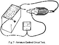
Using a 12-volt battery, voltmeter and test prods, make the test connections shown in Fig.7.
Keep one test prod in contact with the end of the armature shaft and place the other on each commutator segment in turn.
There should be no voltmeter readings. Any segment on which a reading is obtained will be connected to the armature coil nearest an earth fault.
An alternative method is to use a test lamp instead of a volt meter - the lamp will glow if there is an earth. - Unscrew the two pole-shoe retaining screws by means of a pole-shoe screwdriver as shown in Fig. 12. [3]
- Draw the pole-shoe coils out of the yoke and lift off the coils.
- Fit the new field coils over the pole-shoes and place them in position inside the yoke. Take care to ensure that the taping of the field coils is not trapped between the pole-shoes and the yoke.
- Locate the pole-shoes and field coils by lightly tightening the fixing screws.
- Fully tighten the screws by means of the pole-shoe screwdriver.
- Solder the terminal blade and earthing eyelet to the appropriate coil enes.
- Refit the insulating sleeve and re-rivet the terminal assembly to the yoke.
- Refit the insulation piece behind the junction of the two coils.
- Connect a 12-volt battery and bulb in series with two pointed test prods.
- When the prods are placed on the brush tappings, the bulb should illuminate. Lighting of the lamp does not necessarily indicate that the field coils are in order. It is possible that a field coil may be earthed to a pole-shoe or to the yoke.
- Drill out the rivet securing the field coil terminal assembly to the yoke and remove the insulating sleeve from the terminal blade.
- Unsolder the terminal blade and earthing eyelet.
- Remove the insulation piece, which is provided to prevent the junction of the field coils from contacting the yoke.
- Mark the yoke and pole-shoes so that the latter can be fitted in their original, positions.
- Using the pole-screw screwdriver, unscrew the four pole-shoe retaining screws.
- Remove the insulation piece, which is fitted to prevent the intercoil connectors from contacting the yoke.
- Mark the yoke and pole-shoes in order that they may be refitted in their original positions.
- Draw the pole-shoes and coils out of the yoke and lift off the coils.
- Fit the new field coils over the pole-shoes and place them in position inside the yoke. Ensure that the taping of the field coils is not trapped between the pole-shoes and the yoke.
- Locate the pole-shoes and field coils by lightly tightening the fixing screws.
- Refit the insulation piece between the field coil connections and the yoke.
- Finally, tighten the screws by means of the pole-shoe screwdriver.
- The snap rings must be covered by the stop.
- The end of the stop must be peaned down at four points as shown in Fig. 13 to trap the snap-rings in place.
)
The starter motor is a four-pole, two brush unit having an extended shaft, which carries the starter drive, and an integral solenoid switch (see Fig.3).
)
Mechanical Data.
)
Brush length: 1.4 mm (35/64").
Minimum brush length: 8 mm (7/16").
Commutator diameter: 36.5 mm (1 7/16').
Minimum commutator diameter: 34 mm (1 11/32").
Depth of Commutator insulation undercut: 0.5 mm (.020").
Clearance between front stop and pinion when operating: H = 0.5 to 2.5 mm (.020 to .099").
To remove:
)
To replace:
Maintenance:
-
The following checking procedure should be carried out periodically whilst the starter motor is in service.
Testing the Starter Motor.
)
Brushgear.
-
Check that the brushes move freely in their holders by holding back the brush springs and pulling gently on the flexible connectors. If movement is sluggish remove the brush from its holder and clean its sides with a fiuffless petrol-moistened cloth. Replace the brush in its original position. Brushes which are worn to .3125 in. (8 mm.) in length must be renewed. The brushes are preformed so that bedding to the commutator is unnecessary. Check the tension of the brush springs by means of a spring scale. The correct tension is given in 'Technical Data'. New springs must be fitted if the tension is low.
Check the tension of any new spring and ensure that it makes contact with the centre of the brush top.
Commutator.
-
A commutator in good condition will be smooth and free from pits and burned spots. Clean the commutator with a petrol-moistened cloth. If this is ineffective, carefully polish with a strip of fine emery paper, while rotating the armature.
To remedy a badly worn commutator, dismantle the starter drive as described in later paragraphs and remove the armature from the end bracket.
Mount the armature in a lathe, rotate at high speed and take a light cut with a very sharp tool. Do not remove any more metal than is necessary. Finally polish with very fine emery paper.
The insulators between the commutator segments must not be undercut.
Armature.
-
An armature can be tested for open circuits, short circuits, and earthed circuits, by following the procedure described below:
Before carrying out the tests, check for lifted commutator segments and loose turns in the armature winding.
These may be due to the starter motor having remained engaged while the engine was running, thus causing the armature to be rotated at excessive speed.
A damaged armature must always be renewed. No attempt should be made to machine the armature core or to true a distorted armature shaft.
An indication of a bent shaft or a loose pole shoe may be given by scored armature laminations.
Open circuit test:
-
An open circuit, as the term implies, is a break in the armature windings. This defect is characterized by violent sparking at the commutator segment, or in the armature winding, the more usual causes being:
)
Using a 12-volt battery and a voltmeter with test prods, make the connections shown in Fig.8 [13] . Place the voltmeter test prods on each pair of adjacent commutator segments in turn and note the voltmeter readings. If the armature is in good order, all readings will be similar, but if between any pair of segments a low or zero reading is obtained, one or more adjacent coils are open circuited.
Short circuit test:
-
Discoloration of any one or two coils, and blackening of two or more commutator segments is a sign of a short circuit.
The usual causes are as follows:
)
Place the armature in a 'Growler' as shown in Fig.9. Energize the 'Growler' and hold a narrow piece of steel strip over the top of the armature, keeping the steel strip in the same position. If a short circuit exists, the steel strip will be heavily attracted towards the slot containing the faulty coil. If the attraction is particularly heavy, switch off the 'Growler' quickly otherwise the coil may be entirely burnt out.
Remember that a coil is wound in two slots, so that on turning the armature further, a second faulty slot will be found.
Earthed circuit test:
-
An earthed circuit in the armature is caused by a breakdown in the insulation, which will allow a passage of current to the generator frame.
Such a breakdown can be attributed to one or more of the following defects:
)
Field Coils.
-
Continuity test:
-
If the lamp fails to light in the following test, an open circuit in the field coils is indicated and the defective coils must be renewed.
)
Insulation test:
)
Connect a 110-volt A.C. test lamp between the terminal post and a clean part of the yoke.
Lighting of the lamp indicates that the field coils are earthed to the yoke and must be renewed.
Measure the resistance of the field coils without removing them from the starter yoke, by means of an ohmmeter connected between the field terminal and the yoke.
The field resistance is given in 'Technical Data'.
If an ohmmeter is not available, connect a 12-volt D.C. supply between the field terminal and the starter yoke, with an ammeter in series.
The ammeter reading should be approximately 2 amperes.
Zero reading on the ammeter, or an 'infinity' ohmmeter reading, indicates an open circuit in the field winding.
If the current reading is much more than 2 amperes, or the ohmmeter reading is much below 6 ohms, this is an indication that the insulation of one of the field coils has broken down.
In either event, unless a substitute starter motor is available the field coils must be renewed. To do this, carry out the procedure outlined as follows:
Renewing the field coils:
)
This operation should be carried out with the aid of a pole-shoe screwdriver as illustrated in Fig. 12.
Assembly.
-
Assembly is a reversal of the procedure outlined above.
When refitting the starter pinion assembly to the armature shaft, a new front stop must be fitted and the following points taken into consideration.
)
M.4 - STARTER SOLENOID - Section Menu
Adjusting the travel of the solenoid switch operating fork.
)
Energize the solenoid as shown in Fig. 14. [10]
N.B. - Field coil feed terminal (1) must not be connected up. [11]
)
The pinion (2) will then come into its operating position and there should be a clearance H of between 0.5 and 2.5 mm. (.020" to .099") between the pinion (2) and the stop (3).
)
If the clearance is not correct, remove the switch and screw the fork end (4) in or out to obtain the correct clearance.
M.5 - DISTRIBUTOR - Section Menu
- by measuring the Dwell angle by means of a Dwell Meter. This instrument, adaptable from 6 to 12 volts is a standard item of workshop test equipment a and can be used to carry out this measurement either on the test bench or directly on the vehicle without removing the distributor.
- by measuring the points gap with a set of feeler gauges described below:
-
Engage 4th gear.
Rotate one of the road wheels in the forward drive direction, until the contact breaker points are fully opened and check the gap with a gauge having a thickness of from .016 in. to .019 in. (41 mm to 49 mm.)
If the gap is correct the gauge should be a sliding fit.
Do not alter the setting unless the gap varies considerably from the gauge thickness.
To adjust the setting, keep the engine in the position, which gives maximum opening of the contacts and then slacken the screw securing the fixed contact plate.
Adjust the position of the plate until the gap is set to the thickness of the gauge and then tighten the locking screw. Remember that the cam only keeps the contact points fully open over a very small angle and that care must be taken to ensure that the points are in the fully open position.
Cover the hole on the vacuum capsule with the finger and apply the maximum vacuum to the capsule through a vacuum gauge (one can also operate the rod secured to the diaphragm, and to the cam carrier plate by hand).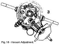
Check that there is the same gap between the two extreme positions of the points i.e.; without vacuum and with maximum vacuum, if this is not the case, turn the cam (see fig. 18) by means of the special key 46M 6184. After carrying out this adjustment re-check that the points gap is still correct.
If the contacts are dirty or pitted, they must be cleaned by polishing them with fine Carborundum stone and afterwards wiping them with a petrol moistened cloth.
The moving contact can be removed from its mounting in order to assist cleaning.
Check and adjust the contact breaker setting after cleaning the contacts.
Check that the moving arm moves freely on its pivot. If it is sluggish remove the moving arm and polish the pivot pin with fine emery cloth.
Afterwards clean off all trace of emery dust and apply a spot of clean engine oil to the top of the pivot.
The contact breaker spring tension is given in 'Technical Data'. - Unclip and remove the distributor cap.
- Remove the rotor arm.
- Undo the nuts securing the low tension and condenser leads to the terminal post sufficiently to release the slotted spade end of the lead to the breaker arm.
- Remove the hair pin clip and withdraw the breaker arm from the pivot post complete with its lead.
- Undo the fixing screw and remove the adjustable contact.
- Locate a new adjustable contact over the guide post and loosely fit the retaining screw.
- Check that the terminal post is fitted correctly into its insulated mounting from within the body of the distributor.
- Interpose the slotted spade end of the contact breaker lead between the square head of the post and the insulated mounting.
- If the leads and nuts have been removed during dismantling it is essential that they be assembled in the correct order.
Proceed as follows:
From outside the distributor body add- the insulating washer
- plain washer
- the eyelet terminal end of the black condenser lead
- plain washer
- spring washer
- secure with the larger nut (10 mm spanner size)
- add the eyelet terminal end of the white/black lead
- lockwasher.
- Secure with the smaller nut (7 mm. spanner size).
- Fit the breaker arm to the pivot post and secure with the hair-pin clip.
Ensure that the leaf spring of the breaker arm is located within the insulation notch. - Adjust the points gap to .016 in. to .019 in. (.41 to .49 mm ) and check gap without vacuum and with maximum vacuum as in previous paragraph.
- Remove the distributor cap.
- Disconnect the white/black low tension lead.
- Unscrew the bolt retaining the distributor clamp on the engine and carefully withdraw the distributor.
- Engage 4th gear.
- Raise the rear right-hand or left-hand road wheel.
- Rotate the road wheel in a forward drive direction until the timing mark on the flywheel is at 4° B.T.D.C. The timing pointer is attached to the flywheel bell housing immediately behind and to the right of the camshaft pulley. Ensure that the first cylinder i.e., at the clutch end is on the compression stroke.
- In this position, the distributor drive pinion must be positioned so that its smallest off-set is on the engine side.
- Refit the distributor.
- Remove the distributor cover and connect a 12 v. bulb between the L.T. terminal on the distributor body and a good earth.
- With the battery connected up, switch on the ignition.
- Turn the distributor in an anti-clockwise direction until the bulb is illuminated. The contact breaker points will then be open.
- Slacken the distributor clamp bolt and rotate the body in an anti-clockwise direction, enough to close the points. Move the body in a clockwise direction again until the lamp just lights, then relock the clamp bolt.
- Remove the distributor.
- Remove the rotor.
- Undo and remove the terminal post from its location in the distributor body.
- Remove the contact breaker points.
- Uncouple the vacuum capsule and remove the unit.
- Remove the condenser.
- Undo the remaining two screws securing the breaker plate to the body and withdraw the plate.
- Undo the 'C' clips at the advance weight pivots.
- Remove the felt pad and unscrew the centre screw and remove the cam.
- Disconnect and remove the advance springs.
- Remove the advance weights.
- Drive out the retaining pin and remove the driving dog and thrust washers from the distributor shaft.
- Withdraw the distributor shaft from the body.
- Remove the spacer washers.
- Using a suitable mandrel located at the body end-drive out the bush.
- Mount the distributor on the tester, and connect the drive from the machine to the distributor dog. Check that the distributor is free to rotate.
- Make the necessary electrical connections (terminal AL on the instrument illustrated to the distributor feed terminal).
- Turn the distributor cam by hand to place the contacts in the closed position and turn the zeroing knob on the instrument to place the pointer on the graduation 100.
Turn the cylinder selector to four, corresponding to the number of lobes on the cam of the distributor. - Run the distributor at approximately l000 rev/min (crankshaft).
-
The number of graduations shown on the instrument give the direct Dwell angle reading.
- Adjust the distributor points to obtain the following Dwell angle reading.
-
New distributor = 61° +- 3°.
Increase the speed up to a maximum of 5,000 rev/min. (crankshaft) and check the dwell reading which must again be 61° +- 3°. If the reading is more than 3° out, check for a worn distributor shaft or bushings. - Make the necessary connections for the stroboscopic timing light or sparking protractor, refer to equipment manufacturer's handbook.
- Adjust the speed control to vary the distributor speed between 400 and 500 rev./min. (crankshaft). Erratic or thin faint flashes of light preceding the regular flashes as the speed of rotation is increased can be due to weak breaker arm spring tension.
- Operate the distributor at approximately 2,500 rev./min. (crankshaft).
- Move the protractor scale with the adjustment control so that the zero degree mark on the scale is opposite one of the neon flashes. The balance of all the flashes should come plus or minus 1°, evenly spaced around the protractor scale. A larger variation than 1° or erratic or wandering flashes may be caused by a worn cam or distributor shaft or a bent distributor shaft.
- Operate the distributor in the direction of rotation (clockwise) [4] and adjust the speed to 300 rev./min. (distributor). Move the protractor scale so that one of the flashes lines up with the zero degree mark.
- Slowly increase the speed and check the advance at the other speeds quoted in the specification. Operate the distributor both up and down the speed range.
)
Contact Breaker Assembly.
At the free After Sales Services (300 miles - 500 km. and 1,200 miles - 2,000 Km.) then subsequently every 3,000 miles (5,000 km.) the contact breaker should be checked and adjusted if necessary.
The distributor points gap can be adjusted in one of two ways:
)
To Remove the Contact Breaker.
To Replace the Contact Breaker.
To Remove Distributor.
To Replace the Distributor and Time the Ignition (Pilot lamp method).
)
)
)
To Time the Ignition Stroboscopic Lamp Method.
-
The use of this method enables the ignition timing to be checked when the engine is running.
When correctly connected, this type of timing lamp gives a high intensity flash each time No. 1 cylinder (flywheel end of engine) fires, and when the beam is projected onto the flywheel this appears to be "stationary" white the engine is running. It is therefore possible to "see" what the ignition timing is with the engine running, and if necessary, to adjust the timing without stopping the engine.
Disconnect the vacuum advance pipe before checking the ignition timing with a stroboscopic lamp, to ensure that the vacuum advance has not begun to operate, thus giving a false setting. Neither should this check be made at a high idling speed.
Distributor Overhaul.
To Dismantle:
To Assemble:
-
Reverse the procedure outlined above.
Distributor Test (off the vehicle)
)
The following instructions indicate the general principles to be followed for testing the distributor on a tester. The method of testing, however, may vary for machines of different manufacture. For specific instructions refer to the equipment manufacturer's handbook.
Mechanical Operation.
Distributor Spark Advance.
-
The spark advance is checked to determine if the ignition timing advances in proper relation to engine speed and load.
Normally this should not require adjustment as it is pre-set during manufacture. However, incorrect assembly, weakening of the advance springs or wear will change curves and rectification will be necessary if engine performance is not to be affected.
M.6 - IGNITION COIL - Section Menu
- Disconnect the leads from the coil (white/black from terminal "RUP" and two white leads from terminal "BAT') (see Fig.23).
- Disconnect the red H.T. cable to distributor by sliding the protective sleeve back and pulling the cable from the socket.
- Release the two securing bolts and remove the coil.
- Reverse the procedure outlined above.
- Connect the leads to the coil, noting the coil polarity.
)
To Remove.
To Replace.
M.7 - SPARKING PLUGS - Section Menu
- Clean the area around each plug to ensure that no foreign matter can enter the cylinder.
- Disconnect the plug leads and remove plugs.
To maintain peak sparking plug performance, the plugs should be cleaned and their points adjusted every 6,000 miles (10,000 km.). The plugs should be renewed at intervals of every 12,000 miles (20,000 km.). Under certain fuel and operating conditions, particularly extended slow-speed town driving, sparking plugs may have to be serviced at shorter intervals.
General:
-
Gap:
The sparking plug gaps, when correctly set, ensure good ignition under all conditions of engine operation. If the gaps are set, or become too wide, misfiring can occur and cold starting may become difficult. Plug gaps set close can cause rough idling and misfiring. Set gaps to the dimension given in 'Technical Data'.
Operating temperature:
Sparking plugs that run too cold will become fouled with combustion deposits under town driving conditions, and plugs that run too hot will fail under hard motorway driving. These failures can also be caused by engine faults producing conditions that the plugs cannot withstand.
Sparking plug temperature is controlled by the construction of the-plug insulator, particularly inside the plug body. The insulator of a correct plug, operating under conditions for which the plug was chosen, will allow sufficient heat flow to give the plug a normal life, and also retain enough heat to keep the plug insulator clean inside the plug body. This ensures that the sparking plugs will operate correctly for their recommended servicing period.
Heat range:
-
Sparking plug manufacturers grade their plugs into 'cold' and 'hot', or 'hard' and 'soft' ranges. From these a suitable plug is chosen as specified in 'Technical Data'.
Corona discharges:
-
This discharge can only be seen in darkness and must not be mistaken for HT discharge shorting across the sparking plug insulator. When occurring, it is seen as a faint blue light in the plug insulator above the plug metal body, and is caused by the HT field in the plug insulator.
Corona discharge can repel dust particles from the plug insulator so that a clean band is seen around the insulator above the plug body.
It is a mistake to think that this is evidence of gas leakage past the insulator if the clean band on the insulator is caused by this discharge.
To Remove.
Inspection.
)
-
Look for powdery deposits ranging from brown to grayish tan. Electrodes may be slightly worn. These are signs of sparking plugs used under normal conditions of mixed periods of high and low speed driving.
Cleaning and re-gapping of the sparking plugs is all that is required (see Fig. 24). White to yellowish powdery deposits usually indicate long periods of constant speed service.
These deposits have no effect on performance if the sparking plugs are cleaned thoroughly and the gaps reset at the recommended intervals.
More frequent cleaning may be needed if the car is only used for short runs.
)
-
This is illustrated in Fig.25. Any spark plugs found in this condition should be replaced by the correct type given in 'Technical Data'. A complete set should be fitted.
)
-
Is usually identified by wet sludge deposits traceable to excessive oil entering the combustion chamber through worn rings and pistons, excessive clearances between intake valve guides and stems or worn bearings etc. (see Fig. 26).
The excessive use of upper cylinder lubricant can also cause fouling.
)
-
Is usually identified by dry black fluffy deposits, which result from incomplete combustion (see Fig. 27). Too rich an air-fuel mixture or incorrect use of the choke can cause incomplete burning, in addition defective contact breaker points or H.T. cables can reduce voltage supplied to the sparking plug and cause misfiring.
If fouling is evident, sticking valves may be the cause. Excessive idling, slow speeds or stop-and-go driving can also keep plug temperature so low that normal combustion deposits are not burned off.
)
-
Burning or overheating of the sparking plug is usually identified by a white burnt or blistered insulator nose and badly eroded electrodes (see Fig. 28). Inefficient engine cooling ad incorrect ignition timing can cause general overheating. If only a few sparking plugs are overheated, the cause may be uneven distribution of the coolant, Severe service, such as sustained high speed and heavy loads, can also produce abnormally high temperatures in the combustion chamber, which necessitates use of colder running sparking plugs.
Cleaning, Testing and Adjustment:
)
Plugs should be cleaned in a dry abrasive cleaning machine and then tested under pressure.
Excessive cleaning time must be avoided because the abrasive cleaning action can erode the electrode insulator.
Before testing, the sparking surfaces of the electrodes should be lightly filed to remove all traces of burning and to restore flat parallel sparking surfaces.
The gap should then be set to the recommended dimension given in 'Technical Data'.
The gap setting of sparking plugs is very important and adjustment is made by bending the earth electrode with a combined gauge and setting tool, as shown in Fig. 29.
After cleaning and gap setting the plug threads should be wire brushed to remove any accumulation of carbon or abrasive material.
A small quantity of graphite grease should be put on each sparking plug thread before the plugs are replaced.
To Replace.
-
Refit the plugs, tightening them to the torque loading given in 'Technical Data'. Reconnect the plug leads.
M.8 - FUSE UNIT - Section Menu
- Disconnect the battery.
- Note positions of all cables, then pull off from the 'Lucar' terminals.
- Remove fuse unit from car, by unscrewing the central cross head securing screw.
- The fuse unit cannot be repaired so can only be replaced with a new unit.
- To replace a blown fuse unclip the cover and remove the fuse from its spring clips, push the new fuse in place an/ replace the cover (obtain replacement 35 amp. fuse if spare is used.)
)
Description.
-
The fuse unit is mounted on the right-hand side of the back bone tunnel below the instrument panel and is readily accessible from within the vehicle.
The unit is of plastic construction having a rectangular base with an integrally moulded fuse compartment.
The fuse compartment houses two fuses, which are held by clips terminated in 'Lucar' connectors.
Two spare fuses are carried in the fuse block, the whole unit being protected with a push-on plastic cover. (Fig. 30).
If reference is made to the wiring diagrams (at the end of this Section) [5], it will be seen which circuits are protected by the fuses.
Wiring diagrams are included in the printed copy only. Online wiring diagrams are available here. [JJ].
To Remove.
To Replace.
M.9 - WINDSCREEN WIPER - Section Menu
- Disconnect the battery.
- Undo the clip retaining the flexible hose from the de-mist nozzle to the heater unit adjacent to the wiper motor.
- Pull the hose from the nozzle and heater outlet and remove it.
- Release the nut securing the bundy tubing to the wiper motor.
- Release the setscrews securing the mounting strap, supporting the motor meanwhile. Ease the motor from its mounting withdrawing the rack from the wheel box and bundy tubing.
- When the wiper motor unit is sufficiently clear of obstruction, disconnect the leads at the motor.
- Replacement is a reversal of the removal procedure, but ensure that the rack is adequately greased before refitting.
- Lift blade and arm clear of the screen, then from underside of arm raise spring clip and pull off blade.
- When replacing, ensure the locating 'pip' on arm is fully entered into the hole on the underside of blade.
- Lift the spring retaining clip and slide the arm from the spindle.
- Operate the wiper for a few moments then switch 'OFF'. This action will allow the wiper spindle to automatically return to the 'park' position, provided the ignition has remained in the 'ON' position.
- Refit the arm in the 'park' position, operate the wiper and check the arc of operation. The serrations on the wiper spindle provides 5° adjustment steps for the arm.
- Disconnect the battery.
- Remove the wiper arm and the wiper motor.
- From the wiper spindle remove the nut, washer and rubber bush securing the wheelbox to the body.
- From behind the facia, pull the wheelbox from its location, passing down into the car from above the heater unit.
- Replacement is a reversal of the removal procedure, but ensure the rubber bushes are correctly fitted to the contour of the body.
- When the sharp wiping edge of the, blade wears off, it becomes rounded so that it is unable to remove atmospheric film or smear from the windscreen.
Use methylated spirits to remove oil, tar spots and other stains from the windscreen.
Silicone and wax-based polishes must not be allowed to contaminate the screen or wiper blades. - Blades are normaliy made from natural rubber, which is the best possible material for cleaning screens, but exposed to the elements at the front of the car, this often deteriorates with age. The warning signs are perishing or cracking, both of which indicate the need for replacement.
- Check the metal harness for wear. Worn arm connectors and worn blade clips can cause the blade to lay over excessively. This not only means a poor wipe because the blade is at an incorrect angle, but can also result in scratched windscreens.
- Rough handling of the wiper arm - particularly while washing the car - can cause twists, and bends in the arm or blade connector. This stops the blade flowing the contour of the screen properly.
- It is important that the blade should be applied to the screen at the correct, pressure. This pressure is transmitted to the blade via the arm hinge. The action must be free of binds and apply firm pressure at the blade connection. The hinge points should therefore be checked for corrosion or wear.
)
Description.
-
The windscreen wiper motor comprises a two-speed electric motor and gearbox driving a cable rack mechanism, which transmits power to the wheelbox spindles and so to the wiper arms and blades. Rotation of the motor armature is converted to a reciprocating motion of the cable rack by means of a single-stage worm and gear, a connecting rod and a cross-head contained in a guide channel.
A switching feature ensures that the arms and the blades return automatically to the 'park' position irrespective of their positions at the instant of switching off. This is effected by a limit switch in the gearbox, its action being controlled by the crankpin. For the greater part of each stroke the limit switch contacts are closed, providing and earth return for the motor current parallel to the facia switch. Each time the blades reach their position at which they are normally parked when the wiper is not in use, the limit switch opens.
Thus, when the control switch is selected OFF, the motor continues to run until the blades reach their parked position.
Service.
-
The windscreen wiper motor is greased during manufacture and no maintenance is required.
The wiper blades operation and arc should be checked at intervals of every 6,000 miles (10,000 km.).
Testing and Adjusting.
-
Measuring supply voltage:
-
Using a moving-coil voltmeter, measure the voltage between the motor supply terminal and a good earthing point. This should be 13.5 + .25 volts with the wiper working normally. If the reading is low, check the battery switch (by substitution), cabling and connections.
Measuring light running current and speed:
-
Connect a moving-coil ammeter in the motor supply cable and measure the light running current. Also observe the operating speed by timing the speed of rotation of the rotating crank. With the linkage system connected, the light running current should not exceed 1.5 amperes with the wiper operating switch in the 'NORMAL' speed position. With the switch in the 'HIGH' speed position, the current should not exceed 2.0 amperes.
The gear speeds should be:
-
NORMAL 46 - 52 r.p.m.
HIGH 60 - 70 r.p.m.
It is important to note that the two-speed effect is only apparent when the screen is very wet. This is quite normal and is due to the decrease in motor torque when 'HIGH' speed is selected at the switch.
Removing and Replacing.
-
Motor:
Blade:
Arm:
Wheelbox:
Wiper Arm and Blade.
Windscreen Washer.
-
A manual type windscreen washer is fitted as standard equipment to the vehicle. This is a combined control assembly consisting of a washer pump and the wiper switch, the control knob for the wipers also actuating when depressed, the bellows of the pump.
Where either the switch or the pump becomes defective it will be necessary to renew the complete assembly, which is retained in the facia by a slotted ring nut. This nut can be removed, after the removal of the control knob, by making up a small tool to engage the slots of the nut. Using a 2 in. (5.1 cm.) length of .75 in (19 mm.) O/D, 14 SWG (.08 in.; 2.03 mm.) steel tubing, one end of which should have two lugs ground to engage the slots in the nut. To the other end is welded a small bar to form a 'T' shaped tool.
- Detach the two leads (green and purple/blue).
- Release the two nuts and bolts securing the horn mounting bracket. The two nuts will be found within the nearside front wheel-arch.
Note the penny washers beneath the securing nuts. - Remove the horn unit as an assembly.
)
Description.
-
The Lotus Europa is fitted with a Clear Hooters miniature wind-tone horn, operated on the well known principle of a resonating air column vibrated by means of a diaphragm actuated electro-magnetically by a self interruptory circuit.
Maintenance.
-
Before being passed out from the manufacturers, every horn is adjusted to give its best performance. It should require no further attention until it has given a long period of service.
If the horn fails to sound or its performance becomes uncertain, the fault may not necessarily be in the horn.
First see that the trouble is not due to such defects as a loose or broken connection in the wiring of the horn circuit or to a discharged battery.
A short circuit in the horn wiring will cause the fuse (when fitted) to blow. In this event, examine the wiring for the fault and rectify accordingly, before renewing the fuse with the spare provided.
A check should also be made to see that the green earth lead is a tight fit in its connector (to boost fan).
If the examination shows the above points to be in order the horn may need adjustment but this should not become necessary until the horns have been in service for a long period.
To Remove.
To Replace.
-
Replacement is a reversal of the above procedure.
Adjustment
)
It should be noted that adjustment does not alter the pitch of the note but merely takes up wear of moving parts.
While adjusting, short out the fuse (if fitted), otherwise it may blow. If a horn does not sound
after making an adjustment, release the horn push instantly.
A small serrated adjustment screw is provided on the side of the horn at which the leads terminate. Turn this screw anti-clockwise until the horn just fails to sound, then turn it back for about a quarter of a turn.
Note: a 12-volt horn in correct adjustment will pass 3.0 - 3.5 ampers; measured on a first grade moving coil 3-10 A ammeter.
If a suitable instrument is available, connect it in series with the horn and turn the adjustment screw clockwise to increase the current, or anti-clockwise to decrease it.
When adjusting a horn with the aid of an ammeter, the aim is obtain the best performance with the least current.
AIR HORNS (optional extra) - Section Menu
- Pull off the vacuum pipes from the horns.
- Release the nuts and bolts securing the horns mounting bracket and remove as an assembly. Turn the assembly over and remove setscrews securing horns to bracket.
- Disconnect the battery.
- Disconnect the cables from the compressor.
- Pull off the vacuum pipe from compressor.
- Loosen the bolts securing the bracket (integral with compressor), lift up and out of car.
- Secure the horns to their mounting bracket with set screws.
- Irrespective of which way the horns mounted before removal, it is recommended that they be mounted with the trumpets inclined slightly downward to avoid the possible ingress of road filth.
- Replace the vacuum pipes.
- Replacement is a reversal of the removal procedure outlined above.
)
-
The air horn kit consists of two matched trumpets and a compressor, which is energized through a relay and switch.
Maintenance.
-
No maintenance is required in service other than the application of a few drops of light oil to the compressor at intervals of every 3,000 miles (5,000 km.) through the orifice marked 'OIL'.
To Remove.
Horns:
Compressor:
To Replace.
Horns:
Compressor:
Installation of the air horns.
-
Mount the trumpets, compressor and relay as shown in Fig. 34.
Tape up end of original horn feed wire (green). Replace terminal on horn push connection (purple/black) with 3/16" ring terminal and connect to 'PUL' on horn relay. Run purple 28/.012 wire from purple wire on radiator fan relay to 'BATT' on horn relay (using pick-a-back Lucar connector at fan relay end, and a 3/16" ring terminal at horn relay end). Connect 'TR' on horn relay to compressor with purple 28/.012 wire with 3/16" ring terminals at either end. Earth compressor with lead using Ľ" ring terminal under the fan fixing bolt, and 3/16" ring terminal.
Earth compressor with 28/.012 lead using Ľ" ring terminal under the fan fixing bolt, and 3/16" ring terminal at compressor end.
- Insert the tool (Fig 35) [14] between the front bezel and the front rim, sliding round to bottom of the rim. Give a sharp tug in an upward and forward direction with the tool, whereupon the front bezel will be pulled clear of the front rim.
- Remove the three cross-head screws securing the front rim to the seating rim and withdraw the front rim.
- Lift the light unit from its location and detach the adaptor (cable connector plug) from the rear of the main bulb and pull the pilot holder from its location in the rear of the reflector body.
- Remove the main bulb from the rear of the reflector body by disengaging the two ends of its spring retaining clip so that the clip is released from the pair of securing tabs, which are formed on the bulb seating ring.
- Remove the pilot bulb by applying slight pressure and turning in an anticlockwise direction from the bayonet location in the holder. To remove the bowl.
- Remove the lamp bowl assembly by undoing the two cross-head screws securing the bowl to the body of the vehicle, and detaching the leads at the snap connectors under the front lip of the luggage compartment lid.
- Remove the rubber gasket and check the condition of the spire nuts in the wings.
- Insert the tool (Fig. 35) between the front bezel and the front rim, sliding round to bottom of the rim. Give a sharp tug in an upward and forward direction with the tool, whereupon the front bezel will be pulled clear of the front rim.
- Remove the cross-head screws securing the front rim to the seating rim and withdraw the front rim.
- Lift the light unit from its location and detach the adaptor (cable connector plug).
- This is a reversal of the removal procedure, but ensure adaptor is fully entered on the projections at the rear of the light unit.
- When fitting the front bezel, hook on the top first then push over its clip at the bottom.
- Ensure that the car is parked (handbrake on) on level ground.
- Ensure that the front of the car is parallel with the aiming board, which is to be positioned at a distance of 25 ft. (7.62 m.) from the car.
- Either load the car with two adults or simulate this load.
- Clean the glass of one lamp.
- Adjustment is to be commenced at one lamp; mask the remaining lamp.
- Turn the adjusting screws clockwise to their full extent.
- With the lamp illuminated in the main beam condition, turn the adjusting screws anti-clockwise as necessary until the required setting is achieved.
- Remove the mask from the remaining lamp and mask the lamp, which has been set.
- Clean the glass of the lamp.
- Turn the lamp adjusting screws clockwise to their full extent.
- With the lamp illuminated in the main beam condition turn the adjusting screws anti-clockwise as necessary until the required setting is achieved.
- Recheck the setting of both lamps.
- Remove the two cross-head screws retaining the lens to the body.
- The bulb is now accessible and can be renewed from its bayonet fixing holder by giving it a slight push and an anti-clockwise movement.
- Fit a new bulb, ensuring that it is correctly tensioned in its holder.
- Refit the lens and secure with the two retaining screws, correctly locating the foam rubber seal and avoiding overtightening. Bulb replacement No 382 12V-21W.
- Remove the two cross-head screws retaining the clear lens in the rear lamp cluster.
- Remove the bulb by pushing gently and turning anti (counter) clockwise.
Bulb replacement Part No 382-12v.- 21w. - Remove the two cross-head screws retaining the red lens in the rear lamp cluster.
- Remove the bulb by pushing gently and turning anti (counter) clockwise.
Bulb replacement: Part No 380 - 12v - 21/6w. - Remove the two cross-head screws retaining the amber lens in the rear lamp cluster.
- Remove the bulb by pushing gently and turning anti (counter) clockwise.
Bulb replacement: Part No. 382 - 12v - 21w. - Remove the four cross-head screws securing the lens.
- The stop/tail and flasher bulbs are removed by pushing and turning anti (counter) clockwise.
The reverse lamp bulb is removed by pressing down on one end then lifting up and out. - Remove the two screws retaining the cover and lens.
- Push bulb contacts to one side and pull bulb from the contacts.
- Replace by pushing bulb into position, and refit cover, and lens. Do not forget to replace rubber sealing washer on screws. (Interposed between body and lens assemblies).
Do not over-tighten screws.
Bulb replacement: Part No.254 – 12v – 6w.
Head lamps
-
Description
-
Each headlamp consists of a detachable light unit incorporating a 'pre-focus' bulb and separate 'pilot' bulb, secured between a front rim and an adaptor housing by retaining screws. This assembly is fitted into the lamp body by a spring and two beam aiming (trimming) screws, the lamp body in its turn being fixed with a seating gasket to the headlamp orifice in each wing.
A bezel clipped to the front rim conceals the fixing screws and provides embellishment.
The design of the headlamp and its holder is such that the bulb is correctly positioned in relation to the reflector and consequently no attention to focusing is required when a replacement bulb is fitted.
The construction of the light unit ensures that the reflector surface is effectively protected. The outer surface of the 'Block-pattern' lens is smooth to facilitate cleaning, but the inner surface has formed in it a series of small lenses, which determine the spread and pattern of the light.
Double filament bulbs are contained in each unit, one for the main beam and the other for the dipped beam. A hand operated dipping switch mounted on the steering column deflects both headlamp beams downward to avoid dazzle.
Certain countries have lighting regulations to which the foregoing arrangements do not conform and vehicles exported to such countries have suitably modified lighting equipment.
Bulb replacement (European Type).
)
The headlamps fitted to left and right hand drive cars for use in European countries are fitted with special front lenses giving an asymmetrical light beam to the right hand or left hand side respectively.
Access to the bulb is as follows:
)
To Replace.
-
This is a reversal of the removal procedure, but ensure leads are connected correctly in their snap connectors, and that the adaptor is fully entered on the terminal projections at the rear of the main bulb.
When fitting the bezel, hook the top on first, the push over its clip at the bottom.
Bulb replacement North America (Federal) type.
)
The headlamps fitted in the above application are of the sealed beam type see Fig. 37.
Each headlamp consists of a sealed beam light unit secured between a front rim and a seating rim, these being held together by rim retaining screws.
This assembly is fitted into the lamp body by a spring and two beam aiming (trimming) screws, the lamp body in its turn being fixed with a seating gasket to the front wing. A bezel clipped to the front rim conceals the fixing screws and provides embellishment.
The sealed beam units are of all-glass construction with an internally aluminized glass reflector fused to the front lens.
Two filaments are contained in each unit, one for the main beam and the other for the dipped beam. These are installed with absolute care and precision before they are finally sealed in the gas-filled chamber of the unit.
The fact that the sealed beam unit is completely sealed ensures that the reflecting surface is protected to the extent of producing continual reflective efficiency without deterioration.
In the event of headlamp failure and where the cause is not due to loose or broken connections, the fault will lie in the sealed beam unit, in which case the unit will require renewal.
To Remove.
To Replace.
Beam Adjustment.
)
Each headlamp is provided with two adjusting screws, the adjusting screw 'A' provides adjustment in the horizontal plane whilst the adjusting screw 'B' provides adjustment in the vertical plane.
It is desirable to use a reputable brand of spirit-level type beam setter if the best standards of accuracy and speed are to be obtained.
Advice is available on application to Lotus Cars (Service) Ltd, in respect of all factory-approved equipment.
)
Should a spirit-level type beam setter not be available, a fair degree of accuracy can be attained by use of an aiming board (Fig. 39). [15]
Beam Setting Using Aiming Board.
Front Flasher Lamps : (Lucas L691).
)
-
These lamps are mounted on the front of the vehicle and are used to convey the intended direction of the vehicle to other road users.
Each lamp has a die-cast metal body on which is mounted a single piece plastic lens, and a bayonet fixing holder for the single contact bulb. The lens piece for the flasher lamp is generally coloured amber for most territories, the exception using a clear lens.
Series One vehicles have their flasher lamps mounted on each front wing below the bumper line, and Series Two vehicles above and inboard of the headlamp units.
Bulb renewal.
Rear Lamp Units.
-
Description.
-
These units are mounted to the rear body panel and incorporate a stop/tail flasher, and reversing lamp.
The unit consists of a die cast body with detachable lenses.
)
Series One vehicles use rear lamp units of Carello manufacture in which each lens and bulb holder is separately detachable. (see Fig. 41). [6]
)
Series Two vehicles employ Lucas L 807 units, each cluster having a single piece detachable lenses, which embrace the various lamp compartments and includes reflectors (See Fig. 42). [6]
Bulb Removal - Series One Vehicles.
Reversing lamp.
Stop/Tail Lamp.
Rear Flasher Lamp.
Bulb Removal - Series Two Vehicles.
Number Plate Lamp:
)
Interior Lamp:
)
Pull bulb holder and lens downwards. Replace bulb and refit by pushing bulb holder and lens into position.
Bulb replacement: Part No. 254 - 12v - 6w.
Side Flasher Lamp:
)
-
Remove the single screw retaining the lens.
Replace bulb and refit lens, taking care to insert the lip of the lens into bezel, before fitting screw.
Do not over-tighten screw.
Bulb replacement : Part No. 501 - 12v- 21w.
Instrument Illumination:
-
Bulb renewal.
-
All instrument illumination bulbs are removed from the rear of the facia panel. The bulb holders themselves being a push flit into the rear of each instrument.
Bulb replacement, Part No. 987 - 12v - 2.2w.
Warning lamps:
-
Bulb renewal.
-
All warning lamp bulbs are removed from the rear of the facia panel.
Warning lamps fitted within instruments on Series One vehicles, have push fit lamp holders in the rear of the instruments themselves.
Federal vehicles equipped with brake and hazard warning lamps mounted in the facia panel are similarly accessible from the rear.
Bulb replacement, Part No. 987 - 12v - 2.2w.
M.12 - DIRECTION INDICATOR SYSTEM - Section Menu
Description.
The correct operation of direction signals requires that the flasher filament in the lamp bulbs (depending on the position of the switch) flash intermittently whether or not the headlamps, parking lamps, tail lamps or stop lamps are 'on'.
A correctly operating direction signal will be indicated by a regular intermittent flashing of the warning lamp located on the facia panel.
If when the ignition switch is on and the direction indicator is operated, the warning lamp does not flash in the usual manner or remains unlit, first check that this is not due to filament failure in either the front or rear on that side. This can be checked by turning the switch to the opposite side - if the warning lamp now flashes, the circuit is in order and bulb replacement is indicated. On the other hand, if the warning lamp still does not flash, inspect the indicator lamps If these are working normally, failure of the warning lamp bulb is indicated.
If, however, the indicator lamps are not functioning, it will be necessary to proceed to check the wiring and flasher unit. The efficiency of the flasher unit may be readily checked by plugging in a known good substitute. The inoperative flasher lamp bulbs should be checked for a burned-out filament. Where it is found that neither lamp has a burned-out filament, the wiring between the defective lamp and indicator switch must be checked.
If the direction signal is entirely inoperative, check the fuse (see wiring diagram) flasher unit and circuit from the fuse box up through the steering column switch in the order named.
The flasher unit is located behind the facia panel below the face level vent on the driving side. No servicing of the flasher is required; where this unit breaks down in service it should be renewed.
Operation.
)
The unit depends for its operation on an electro-magnet in conjunction with the linear expansion of a piece of wire, which becomes heated as current flows through it. The expanding and contracting of the wire controls the speed at which the armature carrying the moving contact will move, as a result of the pull exerted by the electro-magnet. The sequence of operations is as follows: As current flows from terminal 'B' to terminal 'L' and the lamps via the resistance wire and electromagnet, the wire heats up and expands.
This allows the armature carrying one of the contacts to be attracted at the pole piece of the electro-magnet closing contacts (A) and full voltage is then applied to the lamps via the windings of the electromagnet. Contacts (B) are also closed completing the pilot lamp circuit.
While contacts (A) are closed the resistance wire is short circuited and cools off.
The taut section of the resistance wire contracts and pulls back the armature to open contacts (A).
The pilot lamp on the facia panel will not flash unless sufficient current to light the filaments in front and rear flasher lamps is passing through the windings of the electro-magnet to close contacts (B). The flashing pilot lamp therefore, gives the driver a clear indication that the direction signals are working correctly.
It will be noted that in order to maintain the desired rate of flashing the filaments of the front and rear lamps are 'pre-heated' via the resistance wire during 'out' period of the flash.
M.13 - INSTRUMENTS - Section Menu
1. Ignition/Starter Switch.                     14. Main Beam Warning Light.
2. Side/Head Light Switch.            		15. Oil Pressure Warning Light
3. Headlamp Dip Control.                       	16. Choke Control.
4. Direction indicator Control.          	17. Gearshift Lever.
5. Direction Indicator Warning Light.           18. Handbrake.
6. '2-speed' Windscreen Wiper/Washer Control.   19. Clutch Pedal.
7. Steering Wheel.                        	20. Brake Pedal.
8. Ammeter.                    			21. Accelerator Pedal.
9. Water Temperature Gauge.            		22. Ventilators.
10.Fuel Gauge.          			23. Heater Control Flaps.
11. Oil Pressure Gauge. 			24. Heater Control.
12. Speedometer.   				25. Heater/Boost Switch.
13. Tachometer.
1. Ventilators. 17. Ignition/Starter Switch. 2. Steering Wheel. 18. Window Lift Switches. 3. Tachometer. 19. Heater Control Flaps. 4. Ignition Warning Light. 20. Ashtray. 5. Direction Indicator Warning Light. 21. Gearshift Lever. 6. Main Beam Warning Light. 22. Choke Control. 7. Speedometer. 23. Heater Control. 8. De-mist Grille. 24. Accelerator Pedal. 9. Side/Head Light Switch. 25. Brake Pedal. 10. Ammeter. 26. Clutch Pedal. 11. '2-speed' Windscreen Wiper/Washer Control. 27. Direction indicator Control. 12. Oil Pressure Gauge. 28. Trip Reset. 13. Radio. 29. Horn. 14. Water Temperature Gauge. 30. Handbrake. 15. Fuel Gauge. 31. Headlamp Dip Control. 16. Heater/Boost Switch. |
)
)
)
- From behind the facia, pull out the warning lamp bulb holders (Series One vehicles).
- Release the knurled nut securing the drive cable to the instrument.
Remove the trip control to the instrument. - Remove the knurled nuts securing the retaining straps and pull instrument out from front of facia.
- The speedometer driving cable is removed by releasing the lower end from the gearbox, then pulling out the inner cable from this end.
- Replacement is a reversal of the removal procedure.
- Disconnect the battery.
- Pull out the warning lamp bulb holders (Series One vehicles).
- Remove the knurled nuts securing the retaining straps and pull instrument out from front of facia.
- Note locations of cables before releasing.
- Disconnect the battery.
- Remove the knurled nut securing the instrument retaining strap. Pull instrument forward and remove cables.
- When replacing, which is a reversal of the removal instructions, ensure that the gauge is fed with a direct 12-volt supply (non-stabilized).
- Disconnect the battery.
- Remove the knurled nut securing the instrument retaining strap. Pull instrument forward and remove cables.
- When replacing, which is a reversal of the removal procedure, ensure that the gauge is fed via the voltage stabilizer.
- Disconnect the battery.
- Release the valance from below the facia (see Section 'B').
- Remove the knurled nut securing the instrument retaining strap. Pull instrument forward and remove cables.
- Replacement is a reversal of the removal procedure.
- The gauge with its sender unit is connected by its capillary tube and as such, must be removed as an assembly.
- Remove the instrument assembly in a similar fashion to the previously mentioned instruments, after removing the facia valances (see Section 'B').
- Ensure that the cables are correctly connected to their respective terminals.
- Ensure that both the stabilizer and its condenser are correctly earthed via the speedometer mounting or fuel contents gauge (vehicles manufactured 3/69 onwards).
- Maximum permissible 'out-of-true' of the mounting bracket' is 10° in any direction.
Speedometer.
-
To Remove and Replace.
Tachometer.
-
To Remove and Replace.
Oil Pressure Gauge.
-
To Remove and Replace.
Water Temperature Gauge.
-
To Remove and Replace.
Fuel Gauge.
-
To Remove and Replace.
-
The removal and replacement procedure will be found in Section 'L' (Fuel system) of this publication.
Ammeter.
-
To Remove and Replace.
Ambient Temperature Gauge.
-
To Remove and Replace.
Voltage Stabilizer.
-
The purpose of this unit is to stabilize the voltage, which operates the fuel, water temperature and oil pressure gauges, since constant voltage is desirable to ensure correct readings of these instruments.
The voltage stabilizer is mounted directly below the radio aperture and beneath the fuel and water instruments at the rear of the facia panel. The securing bracket MUST be set vertically.
If it is suspected that the voltage stabilizer is faulty, the following procedure is recommended.
M.14 - EARTHING (GROUNDING) OF COMPONENTS - Section Menu
- Centre body mountings (at bottom of facia).
- Rear chassis to body mountings.
As the car body is constructed from glass-fibre-reinforced-plastic (G.F.R.P.) it is most important to ensure that all earthing connections are correctly made.
The main earths are formed by the body to chassis attachments at:
They should be lightly smeared with petroleum jelly or silicone grease.
- Battery.
-
The lead to earth is through the right-hand chassis member via the water pipe mounting bracket. The ring end terminal of the lead is secured to the chassis by a nut and bolt and it is important to ensure that the bolt is threaded throughout its entire length (not shouldered), so that when tightening it can be pulled fully up.
It is equally important to ensure that both battery posts terminals are tight, free from verdigris [7], and protected with petroleum jelly or silicone grease.
- Wiring Loom (Harness).
-
The main loom is earthed (BLACK) cables at the following locations:
- Facia. The correct location is to the left-hand facia to chassis mounting bracket bolt.
- Rear. To the right-hand chassis immediately above the right hand engine support insulator.
- Instrument and Switches.
All of these components are earthed through the wiring loom, therefore it is essential that ALL earth contacts are cleaned of foreign matter or paint BEFORE attaching earth cables. - Earthing Straps.
-
These are fitted at the following locations and it is essential that a GOOD earth exist BEFORE fitting. Remove ALL paint from around the fixing bolt hole.
- Engine to right-hand support insulator.
- Radio to frame (left-hand facia to chassis mounting bracket).
- Rear chassis forks (radio interference suppression kit).
M.15 - SWITCHES - Section Menu
- Facia Switches.
-
To Remove and Replace.
-
Special Equipment:
All switches, with the exception of the window operating switches, can be removed without removal of the facia panel, after first removing the securing nuts.
The window operating switches are secured to the rear of the facia panel by screws. - Horn Switch.
-
To Remove and Replace.
- Disconnect the battery.
- Prise out the centre button from the hub of the steering wheel.
- Lift out the switch brush.
- Reverse these instructions when replacing.
- Direction Indicators Switch.
-
To Remove and Replace.
- Disconnect the battery.
- Remove the binnacle or escutcheons as appropriate.
- Slacken the upper steering column clamp
- Remove the harness cover screw; this is located at the lower end of the harness cover directly above column. Remove harness cover.
- Mark position of cables then release from their snap connectors.
- Remove switch retaining screws and withdraw switch and harness.
- Reverse these instructions when replacing.
- Lighting Switch.
-
To Remove and Replace.
-
The removal procedure is as given under '3' Direction Indicators Switch.
- Relays and Flashers.
- Disconnect the battery.
- Mark the position of cables, then remove.
- Release the securing fixings of the offending relay or flasher unit and remove.
- Replace by reversing these instructions.
Note Re: Radiator Fan Relay.
Some early production cars were delivered with the radiator fan relay position on the inner wheel valance at the side of the radiator. To avoid possible shorting between the relay terminals and the radiator casing, it is recommended that the fan relay be relocated ABOVE and BEHIND the radiator but still on the inner wheel valance. - Ignition/Starter Switch.
-
To prevent the possibility of the ignition/starter switch turning in its location, it is recommended that a lockplate be used as follows:
- Disconnect the battery.
- Using plate (Part No. 36 B 314), measure 1.5 in. (38 mm.) from the long side, which contains the 'D'-shaped hole. Cut plate at this dimension. Bend the four corners of the plate to form small tags, these being at right-angles to the plate.
- Remove the nut from the reverse side of the facia panel, which secures the switch. Add the lockplate with its turned-up corners TOWARDS the panel and replace the nut. As the nut is tightened, the corners on the plate will be pulled into the panel, thus securing the plate and hence the switch.
- Steering Lock.
- Reverse Switch.
-
A check should occasionally be made to ensure that mounting bolts securing the switch bracket to the gearbox are tight and that the switch itself is secure on the bracket.
Early vehicles were fitted with a steel washer beneath the mounting nut.
In order to avoid the possibility of this shorting and causing blown fuses, the washer should be replaced by an insulating grommet (Part No. 36 B 6131).
)
)
M.16 - MOTOR.FAN UNIT - Section Menu
- The electric motor, which drives the fan and its housing.
- The fan.
- The protective fan casing.
- Use a pilot light between terminal 5 on the relay and earth(ground).
If the light does not switch on, check the lead, which connects the battery to terminal 5.
If the light switches on, check the relay coil feed system. - Connect the light between the + on the regulator and earth (ground).
If the light does not switch on, check the connecting lead between the voltage regulator and the ignition switch.
If the light switches on, check the lead, which connects the regulator to terminal (4). - Connect the pilot light between terminal (4) and earth (ground).
If the light does not switch on, recondition or replace the lead.
If the light switches on, check the relay coil. - Connect terminal 2 on the relay to earth (ground).
If the relay does not work replace it.
If the relay works and the motor-fan unit does not run. - Connect pilot light between number 1 relay terminal and earth (ground).
The relay coil is still to be energized.
If the light does not switch on, replace the relay.
If the light switches on, check:-
- the motor feed harness.
- the motor itself. - Remove the lead which connects terminal 2 on the relay to earth (ground) and short-circuit the 2 terminals on the MOSTA temperature switch by means of a lead.
If the motor turns, replace the MOSTA temperature switch.
If the motor does not turn, check the leads connecting:-
- terminal 2 on the relay to the MOSTA temperature switch.
- the MOSTA temperature switch to terminal 3 on the relay.
- Check the relay earth (ground) - (terminal 3).
Description.
-
Above a certain temperature the engine is cooled by a motor-fan unit, which is automatically switched on and off to suit the engine temperature.
This system consists of:
)
- The motor-fan unit itself (electric motor fed with a 12-volt supply and driving a fan).
- A relay mounted near the radiator feeds the current from the battery to the fan.
- A MOSTA temperature switch, which automatically switches the fan on and off to suit the engine temperature.
Temperature at which the contacts close: 82 (+1 .5/- 1)° C (179.6 (+2.7/-1.8)° F) [8]
Temperature at which the contacts open: 68 (+2/-1 .5)° C (154.4 (+3.6/-2.7)° F)
When the coolant temperature in the region of the 'MOSTA' switch reaches 68°C (154.4 F) the MOSTA switch contacts open.
When the coolant temperature in the region of the 'MOSTA' switch reaches 82°C (179.6°F) the MOSTA switch contacts close, the relay coil is energized and its armature is moved over.
The fan motor is fed with current and the fan rotates.
The increase in the air circulation through the radiator and in the engine compartment reduces the coolant temperature.
When this temperature reaches: 68°c (154.4°F), the MOSTA temperature contacts open again, the relay coil is no longer fed with current, the armature is released and the contacts open: the current supply to the fan is switched off.
Removing and refitting the motor-fan unit:
-
Switch off the battery current.
Mark the two leads which feed the motor fan unit so that they are not connected to the wrong terminals when refitting.
Disconnect the two clips, which feed the motor on the control relay R.
)
Dismantling the motor-fan unit.
-
The motor-fan unit consists of 3 distinct parts:
Removing the fan:
)
Unscrew nut (1), which secures the fan to its drive shaft.
Remove the fan (2) forwards.
Warning: It is a left-hand thread.
Remove the fan support and protective casing:
)
Unscrew and remove the screws, which fasten the support to the electric motor body and separate these 2 parts.
Replacing the fan-unit motor carbon brushes:
)
Unscrew the two screws (6) and (7), which secure the rear end plate to the body.
)
Remove the end plate and pull back the brush carrier plate (B).
)
To replace the brushes, unsolder the brush leads at soldering points 9 & 10.
Checking the fan-unit:
Checking the MOSTA temperature switch:
)
The switch should make contact at a temperature T of 82 (+ 1.5/-1)° C (179.6 (+ 2.7/-1.8)° F)
The switch should open at a temperature: T of 68 (+ 2/- 1.5)° C (154.4 (+3.6/- 2.7)° F)
The difference between the temperature at which the contact open and the temperature at which the contacts close should always be greater than 6° C (11° F) and less than 20° C (36° F).
Checking:
-
- Connect a 0.1 amp pilot light between the (÷) terminal of a battery and one of the terminals of the temperature switch.
- Connect the other terminal of the temperature switch to the (-) terminal of the battery.
- The light should not switch on.
- Immerse the lower part of the temperature switch in water which has been raised to a temperature: T + 0.5° C (84° C) (183.2° F)
Before a period of five minutes has elapsed the light should switch on.
- Pour cold water into the tank (whilst keeping the water moving in order to obtain a uniform temperature at all points in the tank. When the temperature of the water has fallen to T - 0.5° C (66° C) (150.8° F) the light should switch out.
M.17 - ALTERNATOR - Section Menu
- Checking principle.
The belt tension is checked by measuring its deflection under a load of 3 m.da N (6 lb 13 ounces).
This check is carried out by special tool Part No. 46M6206. - Description of tool.
The tool consists of: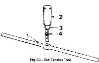
- A bar (1), which rests across the belt, over the two pulley centres.
- A plunger (2), which slides in the bar and permits load to be applied to the belt.
- The plunger body contains a rated spring, which rests on the sliding component (3).
- The sliding component is graduated in millimeters and gives a belt deflection reading.
- A rubber ring (4) is fitted round the sliding component.
- This ring permits one to read the belt deflection after removing the tool from the belt in cases where the belt is in a position to which access is difficult and from which a direct reading cannot be obtained. - Use of the tool: [12]
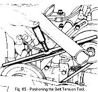
Press the bar against the belt with the plunger approximately half-way between the pulleys.
- Press on the plunger until the shoulder (5) on the sliding part makes contact with the shoulder body. In this position the load of 3 m.da. N is being applied to the belt. At this point: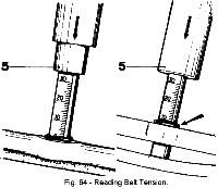
- Take the belt deflection reading from the top edge of the bar, and compare this reading with the figure given in the following list.Adjusting figures.
Deflection under a load of 3 m.da N (6 lb 3 ounces)
On fitting: 7 to 9.5 mm (9/32 to 3/8")
After 2000 kms (1200 miles): 7 to 9.5 mm (9/32 to 3/8").
NOTE - The maximum permissible deflection is 13 mm (33/64").
When the deflection is greater than this, re-tension the belt.
)
Description.
-
A 12-volt S.E.V Motorola alternator, type A 12/30 is fitted to the vehicle.
The nominal output at 30 amps at a constant 3,000 r.p.m when warm is 13.2 volts. The field coil resistance is 5.2 +/- 0.2 ohms [9] at a temperature of 25°C measured across the slip rings.
The unit is robustly constructed and will require very little maintenance in service, as there is no commutator and lubrication is not required.
To remove:
)
Disconnect the battery.
Disconnect the 3 alternator leads:
-
+ terminal.
field terminal (EXC)
earth (ground) terminal (M).
)
Unscrew and remove bolt (A) (which is used to adjust the belt tension) on the tensioner.
Unscrew bolt B which secures the alternator to the cylinder block.
Remove the belt.
To Replace:
-
Replacement is a reversal of the procedure outlined above.
Alternator main feed.
-
The alternator main feed cables should be securely attached to the outlet pipe of the fuel pump using suitable heavy duty tape.
Checking and adjusting the belt tension:
)
)
)
)
ADDITIONAL INFORMATION
M.18 - VOLTAGE STABILIZER - Section Menu
Commencing at Chassis No. 1530, a new voltage stabilizer (Part No. 50 M 6096) has been fitted which is provided with a separate earth terminal, this being directly connected to the earth cable within the wiring loom (harness).
When using the stabilizer as a replacement on earlier cars, fit a 'Lucar' terminal in the place of the ring terminal in order to ensure adequate earthing.
M.19 - IGNITION COIL - Section Menu
Commencing at Chassis No. 0169, the ignition coil is mounted on the front face of the R/H wheel arch.
All coils should be mounted in this position irrespective of where they were originally mounted.
M.20 - CABLE COLOUR CODING - Section Menu
A new system of cable colours has been recently introduced in that cable manufacturers will produce plain colours only and striping of cables will be done by loom manufacturers to suit their own needs. Since it is cheaper, only white cables will in future be striped and these will be distinguished solely by their stripes.
![]()
Two BLUE stripes and one RED stripe on a white base denotes BLUE/RED (see Fig. 67). In the old system this would be denoted by a BLUE ground with a RED stripe.
Two stripes of the same colour denote the base colour and a single stripe denotes the trace colour. Twist the cables to check the stripes, as the natural helix does not make for easy recognition
![]()
Two BLUE stripes on a white base denotes BLUE/WHITE. This is equivalent to two BLUE stripes and a WHITE stripe on a WHITE base (see Fig. 68).
In the old system, this would be BLUE cable with a WHITE stripe. TAKE CARE NOT to confuse, for example, the old type WHITE/BLUE (white cable with a single blue stripe) with the new colour coding.
Plain (self) coloured cables will still continue to be used and both systems (old and new) may occur in the same loom.
M.21 – REVERSE LAMP SWITCH - Section Menu
- With the engine 'dead', select reverse gear, with ignition 'on'.
- With the reverse lamps 'on', bend the actuating bracket of the switch on the gearshift cross-lever, away from the switch plunger until the lamp switches 'off'.
- Bend the bracket back again by 1/8 in. (3.2 mm) so that the lamp is just switched 'on'. After adjustment, crank the bracket so that the part, which is in contact with the switch plunger, is vertical to the plunger.
- With a second operator moving the gearshift lever, check the operation of the switch.
- Finally, apply a liberal coating of silicone grease to the switch and plunger to prevent the ingress of water.
Where difficulty is experienced in switching off the reverse lamps it will be found that this is caused by the operating plunger of the switch over-traveling, thus holding the plunger in the 'on' position.
To adjust the switch, the following procedure is recommended:
- Disconnect the battery.
- Remove the radio aperture blanking piece from the facia panel.
- From the front of the receiver, pull off the control knobs. Remove the nuts now revealed and remove the tuning scale. Locate the speaker lead from behind the facia and connect to receiver. Connect the aerial jumper cable and battery cable inserting the fuse in the latter. Insert the receiver into the aperture in the facia panel and push back sufficiently to enable the side mounting brackets to be fitted. The brackets and fittings are contained in 'package 5' of the 'Fitting and Suppression kit'. Connect the earth braid from 'package 4' to the L/H bracket.
- Move the radio forward so that the front protrudes from the facia panel. Place the chromed bezel from the 'Fitting and Suppression kit' over the front, replace the tuning scale, nuts and control knobs. Connect battery cable to terminal '4' on the ignition switch.
- Remove the trim panel from the door, L/H or R/H, whichever is preferred (see Section 'B').
- At the lower front corner of the reverse side of the panel is a cut-out. Cut the trim to the same shape as the cut-out. Using the speaker grille as a template, mark the four mounting stud holes, drill the holes, mount the grille in the trim panel from the front. From the reverse side of the trim panel, mount the speaker on the grille studs and secure assembly with the plain washers, spring washers and nuts from 'package L.7'. Connect the speaker to the leads in the door and replace trim panel.
- Pull back the trim and felt from the inside of the L/H front corner of the driving compartment.
- Cut a 7/16 in. (11.11 mm) hole in the L/H front wing in such a position that the aerial tube will come just inside the car interior and not into the wheelarch. Mount the aerial, fixing one end of the aerial braid from 'package No.4' of the 'Fitting and Suppression kit' to the earthing bracket on aerial, whilst the other end of the braid is fitted as described under 'Package No.4' in Section 'M.23'.
- The aerial is mounted with its fixings in the following order: aerial with keyed washer, shakeproof washer, earth bracket, earth braid, car body, grommet, insulator, insulator cap, cap nut.
Receiver
-
A radio can be fitted as an accessory in the following manner from Chassis No. 54/0645 (commencement of Series 2 models).
Speaker
Aerial
M.23 - RADIO SUPPRESSION - Section Menu
- Ensure that all metal to metal connections are clean and tight to give good electrical contact.
- The various items of the 'Fitting and Suppression kit' (Part No. 54 M 6048) are supplied in five small packages, mention of which has been made of some of them in Section 'M.22', in addition to the two engine screening plates (Part No. 54 M 0110 and 54 M 0111). The items in each package will be dealt with separately.
- Elongate the mounting holes on the upper plate (Part No. 54 M 0110) and scrape the paint from around the three holes in the flange of the plate. Remove the nut from the bolt on each hinge, which will correspond with the hole and the screws along the inner edge of the engine compartment grilles.
- Fix the plate to the engine compartment lid by replacing the fixings.
- Move the seats as far forward as possible and remove the rear trim panel (see Section 'B').
- Hold the bulkhead screening plate (Part No. 54 N 0111) in position, making certain it is not touching the wiring loom or fuel feed pipe, which pass across the engine compartment at the bottom of the bulkhead. Drill Ľ in. (6.35 mm) holes through the bulkhead using the plate as a template.
- Scrape the paint from around all holes and mount the plate using bolts passed through from front.
)
To give an acceptable reception from the radio, outside interference must be suppressed. This is achieved in the following manner:
General
Screening Plates
Package No. l
-
Remove the ignition coil from its mounting.
Scrape the paint from the mounting area, replace the bracket fixing the clip of the 'l mfd' condenser and one end of the PVC covered earth braid under one of the mounting bolts.
Connect the condenser cable to the 'SW (BAT)' terminal on the coil.
Secure one end of each of the two remaining earth braids, to each of the lower bulkhead screening plates mounting bolts.
Drill two Ľ in. (6.35 mm) holes in the chassis immediately below, scrape the paint and underseal away and secure these braids to the chassis with the nuts and bolts, the nuts being fitted from below the chassis.
Package No. 2
-
Remove the sparking plug cables and fit the suppressors
Cut the HT lead from coil to distributor and fit the '15 ohm' in-line suppressor.
Fit the two '1 mfd' condensers to the alternator earth terminal by their body clips and connect their cables to the main alternator terminal (BROWN cable).
Fit the '.25mfd' condenser to a suitable bolt on the engine, near to the oil pressure sender unit and connect its cable to the sender unit.
Package No. 3
-
Fit the three similar earth braids to connect the two engine screening plates, using nuts and bolts in the three holes in the flange of each plate.
Fit the other two braids, one between the centre hole in the bulkhead screening plate flange and the rear rocker cover bolt, the other between the air cleaner clamp and a rocker cover bolt.
Package No. 4
-
Fit the 11 in. (28 cm.) long earth braid From a radiator fan mounting bolt to the chassis mount bolt below.
Fit the 15 in. (38 cm.) long earth braid from a heater mounting bolt to the chassis mounting bolt below.
Connect the aerial earth braid to the bolt on the end of the wiper motor and to the bottom L/H corner of the heater, by removing the screw at that point and replacing it by a longer one with washer.
Finally, connect the end of this braid to earth using one of the screws retaining the throttle cable bracket to the tunnel side. The radio earth braid should also be connected to earth at this point.
Package No. 5
-
Cut the RED/LIGHT GREEN and BLUE/LIGHT GREEN cables to the wiper motor and fit two-way 'bullet' connectors so that the '1 mfd' capacitor can be plugged in between these cables.
Remove the trim panel from the door.
Fit two '1 mfd' capacitors, one between each of the feed cables to the window motor and the earth screw in the door.
Suppression of the window motor in the R/H door is not necessary, due to its distance from the aerial.
Locate the '10 volt' stabilizer behind the facia panel.
Fit two 'l mfd' capacitors, one between each of the '1' and 'B' terminals and earth.
Fit the '200MH' choke in-line from the 'l' terminal to the instruments.
Note that two types of voltage stabilizers have been used; the early unit had a body earth, whilst the latter type is provided with a terminal earth.
M.24 - REVERSE LAMP SWITCH - Section Menu
- Disconnect the battery. Release the cable from the existing switch and remove switch.
- Remove the plug (just to the rear of the right-hand drive shaft) in the side of the gearbox casing and discard.
- Screw in the new reverse lamp switch (Part No. A065 M 6002) (see Fig. 111 in Section 'F' for location). Attach extension cable (Part No. A054 M 0165) to existing cable and to switch. Reconnect the battery.
An improved reverse lamp switch is now fitted in current production and is available for fitting to existing cars if desired.
Editors Notes:
-
[1] Original text referenced Fig. 4. Corrected to Fig. 5 [JJ]
[2] Original text referenced Fig. 5. Corrected to Fig. 6 [JJ]
[3] Original text referenced Fig. 11. Corrected to Fig. 12 [JJ]
[4] Original text reads (anti-clockwise). This is incorrect. The distributor rotates clockwise when viewed from above. [JJ]
[5] Original text reads (at the end os Section). Corrected to (at the end of this Section). [JJ]
[6] Original text referenced Fig. 40 upper and lower. Corrected to Fig. 41 and Fig. 42. Series 1 vehicles starting at chassis number 460542 used Series 2 rear lamp assemblies. [JJ]
[7] Verdigris is the common name for copper acetate. It's that green stuff that surrounds your battery posts. [JJ]
[8] Removed phrase "92şC +1.5". [JJ]
[9] Added the phrase "+/-". [JJ]
[10] Original text referenced "the above illustration". Corrected to Fig. 14 [JJ]
[11] N.B.: An abbreviation for the Latin phrase 'nota bene', meaning 'note well.' It is used to emphasize an important point. [BB]
[12] Added paragraph heading for clarity. [JJ]
[13] Original text referenced Fig. 7. Corrected to Fig. 8 [JJ]
[14] Original text referenced Fig. 34. Corrected to Fig. 35 [JJ]
[15] Original text referenced Fig. 38. Corrected to Fig. 39 [JJ]
Other Notes: [edit]
This area is a public scratchpad for notes.
Please be courteous with what you post, and do not erase someone else's work.