H.1 - GENERAL DESCRIPTION - Section Menu
The steering gear is of the direct acting rack-and-pinion type, there being no separate steering linkage.
The steering unit is mounted on clamp-type brackets attached to the front cross member of the chassis.
The steering wheel is mounted on a column, which is designed to collapse under heavy impact thus minimizing severe injury to the driver.
Movement of the steering wheel is transmitted by the steering shaft through a flexible coupling to the straight toothed pinion.
Rotation of this pinion causes the rack to move laterally, and the track rods, attached to the ends of the rack, transmit this movement to the steering arms causing the road wheels to turn onto lock.
The steering arms are bolted to the vertical link.
The track rod inner ball joints, attached to the rack, are protected by convoluted rubber bellows and the outer ball joints, which are of the pre-packed lubricated type, are protected by normal gaiters.
Maintenance.
-
Lubrication of the lower swivel bearings (transmissions) is most important to maintain accurate steering (see section 'C' Front Suspension).
The steering unit should be lubricated as indicated in section 'O' (Lubrication and maintenance).
Adjustment.
-
The design and construction of the steering gear provides for two adjustments:
(a) Rack damper adjustment.
(b) Pinion bearing pre-load adjustment. Both these adjustments are obtained by varying the thickness of shim pack under a cover plate.
It is necessary to remove the steering unit from the vehicle to carry out these adjustments.
The track rods are adjustable for length to permit toe-in setting and to ensure that the wheel lock angles are correct, the caster, camber and kingpin inclination angles are built in to the design of the suspension and no provision is made for altering them.
The lock stops provided within rack and pinion unit permit no adjustment.
Warning. - When the vehicle is jacked up so that the front wheels are clear of the ground do NOT move the road wheels quickly from lock to lock.
This may cause serious damage within the steering unit and in any event, the consequential hydraulic pressure built up within the unit may burst or blow off the bellows.
)
H.2 - STEERING WHEEL - Section Menu
To remove.
-
Set the front wheels in the straight ahead position.
Carefully prise out the central horn push button assembly from the hub of the steering wheel.
Withdraw the contact plunger assembly.
Using a suitable socket or box spanner, remove the securing nut, taking care not to damage the three legs of the button retaining clip.
Remove the clip.
Pull the steering wheel from the column.
A straight rearward pull is all that is required as the wheel is splined to the inner column.
To replace.
-
Replacing the steering wheel is a direct reversal of the removal procedure.
Note that no force is necessary to locate the wheel on the splines of the inner column.
Ensure that the wheel is replaced in a straight ahead condition to facilitate the correct location of the horn contact with the plunger assembly.
H.3 - INNER COLUMN - Section Menu
To remove.
-
The inner column is in two parts and can consequently only be removed individually unless the inner and outer columns are removed as an assembly.
From the lower end of the outer steering column, remove the impact clamp.
Using a steady pull, pull the upper column with steering wheel attached, from its location.
Unscrew the two pivot bolts and remove the front luggage compartment lid taking care to note the quantity and position of the spacer washers.
Remove the spare wheel and tool kit etc. from the lower compartment.
Remove the steering unit access panel (secured by nine self taping screws).
Release the pinch bolt retaining the lower inner column to the steering unit pinion coupling, then push the column up into the outer column.
With the aid of a suitable rod, continue pushing the lower inner column up the outer column until it can be removed from the interior of the car.
To Replace.
-
Replacing the inner column is a reversal of the removal procedure.
Check that there is clearance between the underside of the steering wheel hub and the outer steering wheel column.
The 'flats' on the lower column and the 'cut-out' in the upper column should of course be in line with each other to ensure the impact clamp is fitted correctly.
)
Ensure the impact clamp is fully tightened (Fig 2) with the steering column in the midway (up and down) position.
If the clamp is tightened with the column in the fully down position, it will not be able to collapse in the event of an impact.
H.4 - OUTER COLUMN - Section Menu
To remove.
-
Disconnect the battery.
Mark the position of both the headlamps dipswitch and the direction indicator switch cables in their connectors, then release cables.
Release pinch bolt retaining the lower inner column to the steering unit coupling.
From below the facia panel release the nuts securing the upper column clamp. The nuts securing the lower column clamp are accessible from the driver’s foot well.
Remove assembly from vehicle.
Remove inner column (Section H.3) and bushes.
)
)
To replace.
-
Fit the new nylon bushes to their locations in the outer column (see Fig. 3 and 4), so that the securing lugs engage in the holes of the outer column.
The metal reinforcement of each bush is towards the lower end of the column.
Replace inner column.
Replace column assembly into its location and loosely attach the retaining clamps.
Tighten steering unit pinion to inner column coupling pinch bolt after ensuring clearance between hub of steering wheel and outer column.
Fully tighten the two retaining clamps.
Replace the switch cables in their connectors; finally reconnect the battery.
H.5 - STEERING UNIT LOCKSTOPS - Section Menu
)
Limitation of the steering lock (Fig. 5) is controlled by the locknut contacting the rack tube.
)
Thus dimension 3 (Fig.7) is particularly important.
Providing that this dimension is accurate and the steering unit is mounted centrally on the chassis, correct steering locks should result. (See also Section 'C' under Steering Geometry).
H.6 - STEERING UNIT - Section Menu
- Release the clips securing the ends of the bellows and slide both bellows towards the outer ends.
Slacken the locknuts and unscrew both outer tie rod/ ball-joint assemblies from the rack.
Withdraw the spring from each end of the rack. - Release the tab washer, unscrew the sleeve nut and remove the tab washer, shims and cup.
Slacken the locknuts and unscrew the outer ball joint assemblies from the tie rods. - Remove the locknuts, rubber bellows, clips and cup nut from each outer tie rod.
- Remove the locknuts from the ends of the rack.
Unscrew the cap and remove the shims, spring and pressure pad from the housing. - Remove the circlip and withdraw the pinion assembly, taking care not to lose the dowel peg.
Remove the retaining ring, shims, bush and thrust washer.
Detach the rubber 'O' ring from the annular groove in the retaining ring. - Withdraw the rack from the tube and remove the thrust washer and bush from the pinion housing.
- The ball end of the tie-rod for 'necking'.
-
This 'necking' if evident, can be recognized as a groove running around the circumference of the ball-to-rod waist.
If 'necking' has occurred (or if there is any doubt) RENEW the tie rod.
If necessary, renew the bush in the end of the rack tube, by drifting out the old bush and pressing in a new one. - The inboard end of the steering arm ball joints for any possible signs of cracks where they are tightened together with their respective tie rod adaptors (vehicles up to unit No 1904). Where a ball joint is found to be faulty or suspect, discard BOTH joints and tie rod adaptors. Modified adaptors (Part No 54 H056), which will overcome further possible occurrences, should be fitted.
- Insert the rack into the tube and place the bush and thrust washer into the pinion housing.
- Adjust the pinion end float as follows:
- Assemble the thrust washer, bush and retaining ring to the pinion. Insert the assembly into the pinion housing and secure the pinion with the circlip.
- Mount a dial gauge on the tube as shown in Fig. 10.
Push the pinion down to its limit and zero the dial gauge.
Lift the shaft until the retaining ring contacts the circlip and note the dial reading.
This represents the total pinion shaft end float.
Remove the circlip and withdraw the pinion shaft assembly.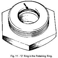
Remove the retaining ring and fit a new rubber 'O' ring (see Fig. 11). - Make up a shim pack to give minimum end float consistent with free rotation of the pinion shaft.
Shims are available in .004 in. (.102 mm.) and .010 in. (.254 mm.) thickness. - Assemble the shim pack and retainer ring to the pinion.
Re-insert the assembly into the housing and finally secure it by fitting the dowel and circlip.
- Adjust the pinion pressure pad as follows:
- Fit the plunger and cap nut to the pinion housing.
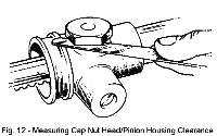
Tighten the nut to eliminate all end float and, using feeler gauges, measure the clearance between the nut and housing as shown on Fig. 12. - Remove the cap nut and plunger.
Make up a shim pack equal to the cap nut to housing clearance, plus .004 in. (.102 mm). - Pack the unit with grease and assemble the cap nut, shim pack spring and plunger to the housing and tighten the cap nut.
- When the nut is correctly adjusted, a force of 2 lb. (.91 kg.) is required to rotate the pinion at a radius of 8 in. (23.3 cm) see Fig.13.
Check and re-adjust the unit, if necessary, by adding or subtracting shims from beneath the cap nut. - Fit the plunger and cap nut to the pinion housing.
- Slide the cup nut over the tie-rod and insert the cup into the cup nut.
- Position the lock tab over the sleeve nut and screw this fully into the cup nut.
With the cup nut held in a vice, move the tie-rod axially to determine the approximate shim pack thickness required.
Remove the assembly from the vice and remove sleeve nut. - Prepare a shim pack in excess of the estimated ball movement and insert this in the cup nut behind the nut (Fig 14).
- Screw the sleeve nut with lock tab fully into the cup nut.
- Using feeler gauges, measure the gap between the sleeve nut flange, lock tab and cup nut face.
This dimension plus .002 in. (.005 mm.) is the amount by which the trial shim pack must be reduced to give the correct ball end movement. - Dismantle the ball joint and re-assemble it with the correct shim pack taking care to avoid sudden tightening of the ball joint.
- Screw the locknut on to the end of the rack so that its position corresponds with dimensions 3 + 4 + 5 + 3 on Fig. 6, i.e., 24.42 in. (62.03 cm) between inner locknut faces.
- Insert the spring into the end of the rack and screw the ball joint assembly as far as possible up to locknut.
- Push the bellows on to the tie-rods. <
- Test adjustment by applying a load of 8 lb. (3.629 kg.) at the outer end of the tie-rod, when the tie-rod should articulate freely.
If necessary, adjust the shim pack until correct operation is obtained.
Shims are obtainable in .002 in. (.05 mm.) and .010 in. (.254 mm.) thickness. - When adjustment is correct, lock the assembly by bending the lock tab over the sleeve nut and cup nut.
- Repack the bellows with grease (˝ oz. of Shell Retinax 'A' or similar) and secure them in position with the hose clips.
- Fit the modified tie-rod adaptors to the ball joints using the ˝ in. (12.7 mm.) spring washers as shown in Fig. 15. [1]
Torque tighten to 50 lbs. ft. (6.91 kg. m.). - Fit the tie-rod locknuts and outer ball joint assemblies to the tie-rods, screwing them on exactly 25 turns, then hand tighten locknuts.
- Fit the steering unit mounting bracket bolts to the chassis cross member.
Attach the base part of each steering unit bracket to the bolts. - Set the hubs in the straight ahead position and check that the steering wheel is also in this condition.
Maneuver the steering unit through the aperture on the driver’s side of the chassis front cross member.
Engage the splined end of the flexible coupling with the inner steering column. - Fit the two bracket caps over the rack tube attaching to the bolts projecting forward through the base part of each bracket.
Replace the washers and Nyloc nuts. (Do not tighten.) - Position the steering unit so that the distance between the inner face of the pinion housing and its adjacent bracket is 11/16 in. (17.4 mm.) See Fig. 9.
- Fully tighten the coupling pinch bolt and the bracket mounting bolts, to a torque loading of 10 lbs. ft. (1.38 kg. m.).
- Replace the ball Joint ends of the tie-rods into their respective steering arms and tighten nuts to the torque loading given in Technical Data.
- Replace front wheels.
- Finally, adjust the front wheel toe-in (see section 'C' Front Suspension) and tighten the tie-rod locknuts.
To remove.
-
Raise the front of the vehicle after applying the handbrake and chocking the rear wheels front and rear.
)
Support the front of the vehicle by placing a trestle or stands beneath the chassis cross member, immediately behind the chassis closing plate in the position indicated in Fig.6.
Remove the front wheels.
Access to the steering rack and coupling is obtained from within the front luggage compartment.
Removal of the rack unit is further facilitated if the chassis closing plate, beneath the vehicle is removed.
Unscrew the two pivot bolts and remove the front luggage compartment lid taking care to note the quantity and position of the spacer washers.
Remove the spare wheel and tool kit etc. from the lower compartment.
Remove the two steering unit access panels (attached by eleven self-tap screws).
From beneath the vehicle:
-
Remove the three bolts and spring and penny washers securing the rear of the chassis closing plate.
Undo the two Nyloc nuts and washers securing the front of the plate.
Remove the two bolts and washers from within the luggage compartment and remove the plate by withdrawing the front lip of the plate from above the anti-roll bar.
Undo the Nyloc nuts from the ball joint on the end of each track rod.
Using a ball joint separator, part each ball joint taper from its steering arm.
)
Undo the four Nyloc nuts and washers from the steering unit clamps and remove the caps.
Move the steering unit forward to disengage the coupling from the inner column, taking care to avoid damaging the brake pipes to the master cylinder.
Maneuver the unit from the vehicle (via the drivers side of the cross member).
)
To Dismantle.
Inspection.
-
Clean and examine all components for wear and damage) renewing parts as required.
It is particularly important to check:
To assemble.
)
)
)
)
Assembling the Tie-Rod.
)
)
To replace.
H.7 - STEERING ARMS - Section Menu
- Remove the vertical link (see Section 'C').
- Extract the lower two bolts securing the brake disc dust cover, the brake caliper mounting plate and the steering arm to the vertical link (see Fig.16).
To remove.
)
To replace.
Replacing the steering arm is a direct reversal of the removal procedure, but noting that they are handed.
Ensure correct replacement.
Tighten bolts to the torque loading given in Technical Data.
Editors Notes:
-
[1] Original labeled 'Fig 13'. Changed to 'Fig. 15'. [JJ]
Other Notes: [edit]
This area is a public scratchpad for notes.
Please be courteous with what you post, and do not erase someone else's work.