F.1 - MODEL IDENTIFICATION - Section Menu
Commencing at Unit No 46/0267, a new gearbox with revised gate pattern was introduced.
If reference is made to the identification tag at the rear end of the gearbox, adjacent to the selector shaft, this will show which type is fitted (either 336/08 or 336/26 or 336/46 or 336/56). [2]
The type, index and manufacturing number are given on a number plate on the front of the housing.
F.2 - OPERATING DIAGRAMS - Section Menu
F.3 - LONGITUDINAL SECTION - Section Menu
F.4 - SECTION THROUGH DIFFERENTIAL - Section Menu
F.5 - SECTION THROUGH THE SHIFT FORKS - Section Menu
F.6 - GEAR SHIFT LOCKING SYSTEM - Section Menu
Each of the shift forks is locked, no matter what its position (whether in neutral or with a gear engaged) by a ball and a spring. Furthermore, the disc (1) locks:
-
- the 3rd-4th speed shafts and the reverse shaft when 1st-2nd gear is engaged.
- the 1st-2nd speed shafts and reverse shaft when the 3rd-4th gear is engaged.
- the 1st-2nd and 3rd-4th speed shafts when the reverse gear is engaged.
F.7 - REMOVING AND REFITTING THE GEARBOX - Section Menu
A - Removing
-
Before commencing operations, place protective coverings on the body sides around the engine compartment. Removal of the gearbox is facilitated if the engine compartment lid is detached. To do this, remove the two nuts and penny washers under each hinge, taking care to note the quantity and position of the spacer washers situated between the cross member and the undersurface of the compartment.
- Disconnect the battery leads.
- Drain the gearbox, using tool (Part No 46E 6167).

- Disconnect the speedometer drive cable at the gearbox.
- Disconnect the leads to the reversing lamp switch and remove the switch
Series two vehicles only:
- Remove the bolt, which secures the reaction rod to the bracket on the gearbox and swing the reaction rod out of the way.
- Replace the bolt and the spacer washers on the reaction rod for safekeeping.
Remove the bolt (or circlip - Series one cars), which secures the rear gear control shaft to the cross shaft lever at the rose joint.

Remove the hubcaps from the rear road wheels, and slightly slacken the nuts. Chock [1] the front road wheels. Raise the rear of the car and support the vehicle by placing stands beneath the chassis at the position indicated. Remove the rear road wheels.
Disconnect the clutch cable from the lever at the bell housing.
Remove the outer flange plate from the camshaft pulley by undoing the four nuts, noting the shims fitted between the two flanges.
Remove the silencer (muffler) assembly:
-
- Undo the nut attaching the horizontal silencer (muffler) strap to the clutch housing.
- Remove the two bolts securing the silencer (muffler) mounting bracket to the gearbox.
- Undo the clip clamping the silencer (muffler) to the front pipe and withdraw the component rearwards.

Unscrew the four nuts retaining the rear cross member to the chassis and remove the mount.
Unscrew the bolts retaining the bottom suspension link to the gearbox bracket, allowing the link to drop clear.

Drive the roll pins from the inner universal joints on the transmission shafts by means of a drift
(Part 46F 6171).
With the chassis cross member and exhaust system removed, it is possible to stand within the confines of the engine compartment thus simplifying this operation.
Care must be exercised that the drift be struck solidly and squarely as light 'tapping attempts' may only succeed in burring the components.
Free the drive shafts from the gearbox output shafts by withdrawing them outwards from their splines, noting the shims fitted on the output shafts.
Unlock and remove the three bolts, which secure the starter and pull it back as far as possible.

Unlock and remove the three bolts, which secure the clutch casing to the engine.

Unscrew the two front mounting pad securing nuts in order to be able to remove the two anchor nuts.
Remove the two bolts, which secure the pad bracket to the front housing.
Remove the pad and its bracket.
Pull the gearbox (transmission case) as far as it will go towards the rear of the car in order to free the clutch shaft.
Lift the rear of the box (take care not to damage the rear bodywork) and remove it vertically.
To prepare the gearbox (Transmission case) for fitting to the dismantling stand it is suggested that the following items be removed:
-
- the suspension lower link mounting underneath the gearbox (Transmission case)
- the front cover plate fitted to the lower half of the clutch housing front.
-
Carry out the removing operations in reverse, paying attention to the following points:
-
- Lightly grease the splines on the clutch shaft.
- Grease the output shaft splines with a graphited grease.
- Place one of the pin holes at the bottom of one of the splines in the transmission shaft, in line with the hole on top of one of the output shaft splines

- When fitting the water pump drive belt, slowly tighten the nuts on the outer flange while turning the engine, in order to avoid damage to the belt.

- To make it easier to fit the transmission shaft roll pins, use the cranked end of drift (Part No 46F 6171).

Check the belt deflection by means of tool (Part46M 2606): it should be: 2.5 to 4 mm (3/32 to 5/32").
NOTE - It is forbidden to use the camshaft pulley retaining bolt to turn the engine.
One must therefore:
-
- Lift one side of the car.
- Engage 4th gear.
- Turn the wheel in the forward drive direction.
- Adjust the clutch clearance.
Fill the gearbox with oil: grade EP 80.
Check and adjust if necessary:
the gear change linkage for freedom of movement and ease of change.
Series Two Vehicles.
For further information on the gearbox linkage see Section 'F.l0.'.
F.8 - OVERHAULING THE GEARBOX (TRANSMISSION) - Section Menu
A - Dismantling.

Secure the gearbox to tool 46F6171, which is fitted to the adjustable stand or the bench stand.

Remove the clutch housing securing bolts.

Remove the rear housing securing bolts and remove the component.

Remove the locking plates from the nuts.
Loosen and unscrew the nuts by means of spanner (wrench) (Part No 46F 6179).

Remove the half housing assembly bolts and separate the half housings.
Remove the spacer and the adjusting shafts from the primary shaft bearings.

Remove the secondary gear cluster and the stud, which locks the outer track ring on the double taper roller bearing.
1 - Gearshift control
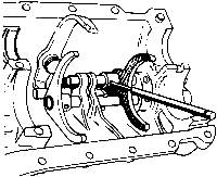
Push out the roll pin from the 3rd-4th shift fork by means of drift (Part No 46F 6180).
Remove the shift fork and the shaft (put aside the locking ball and spring).
Remove the locking disc from between the two shafts.
Engage first gear.
Pull back the reverse shaft as far as possible towards the control end.
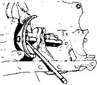
Push out the roll pin from the 1st-2nd shift fork using drift (Part No 46F 6180).
Remove the shaft and shift fork (put aside the locking ball and spring).
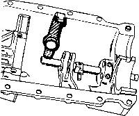
Unscrew the reverse swivel lever pivot pin and take out the swivel lever.
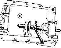
Push out the roll pin from the reverse positioning fork by means of drift (Part No 46F 6180) (the pin will make contact with the housing, turn the shaft and free it completely by means of a pair of pliers).
Remove the shaft and the fork.
2 - Reverse gear wheel
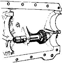
Remove the gear wheel retaining clip and take out:
- the shaft, gear wheel, friction washer and guide (put aside the locking ball and spring).
3. Half-housings
4 - Primary shaft
Remove the bearing track-rings and the adjusting washers.
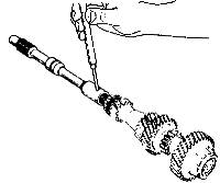
Separate the clutch shaft from the primary shaft by pushing out the roll pin by means of drift (Part No 46F 6171).
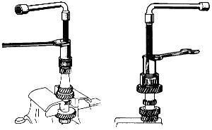
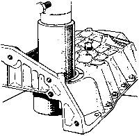
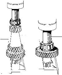
Extract the bearing from the differential end by means of extractor (Part No 46F 6168) fitted with shell (Part No 46F 6172).
Extract the second bearing by means of extractor (Part No 46F 6168), fitted with shell (Part No 46F 6173).
5 - Secondary shaft
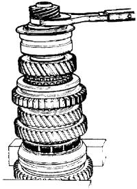
NOTE:
Whenever carrying out any operation on the 1st-2nd speed synchronizer hub, one must use an electric oven capable of achieving a temperature of 250ºC (482ºF) for reassembling.
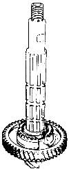
Grip the shaft in a vice on the first speed gear wheel.
Engage 1st speed.
Unlock the speedometer drive worm and unscrew it by means of spanner (Part No 46F 6175).
Remove:
-
- the double taper roller bearing.
- the pinion depth adjusting washer.
- the 4th speed gear wheel and its ring.
- the 3rd-4th speed synchronizer sliding gear wheel and the keys.
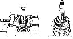
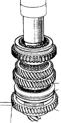
Extract the 3rd-4th speed synchronizer hub on the press by means of extractor (Part No 46F 6181).
Remove:
-
- the gear wheel stop washer retaining key.
- the 3rd speed gear wheel stop washer.
- the 3rd speed gear wheel and its ring.
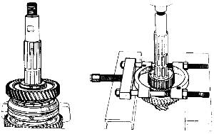
Remove: - the 2nd speed gear wheel stop washer and the 2nd speed gear wheel and its ring.
Remove: - the 1st-2nd speed synchronizer sliding gear wheel (mark its position with reference to the hub)
Remove: - the 1st-2nd speed synchronizer hub stop washer.
Extract the lst-2nd speed synchronizer hub on the press by means of extractor (Part No 46F 6181).
-
- the 1st speed synchronizer.
- the 1st speed gear wheel stop washer.
- the 1st speed gear wheel
NOTE: As the roller bearing inner track-ring is bonded to the shaft, this bearing cannot be removed.
6 - Differential
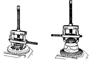
On the crown wheel side, remove two of the securing bolts (loosen them with a cold chisel).
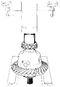
Remove the bearings by means of tool (Part No 46F 6169) fitted with claws (Part No 46F 6174).
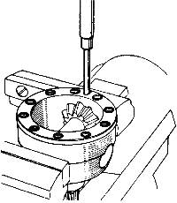
Remove the crown wheel securing bolts (these are self 1ocking bolts which cannot be used again).
Push out the planet wheel shaft roll pin by means of drift (Part No 46F 6171).
Separate the various parts.
7 - Rear housing
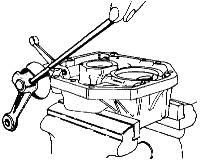
Remove the pinion, the guide and the "O" ring.
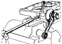
Push out the shift lever roll pin by means of a drift.
Unscrew the breather.
Push out the roll pin from the internal shift lever through the breather hole by means of a drift.
Take out:
-
- the lever,
- the rubber,
- the shaft,
- the internal lever.
8 - Cleaning and checking
Clean and check all the parts.
All seals and gaskets, roll pins and self locking bolts should be replaced by new ones.
B - REASSEMBLING THE SUB-ASSEMBLIES - Section Menu
1. Secondary shaft
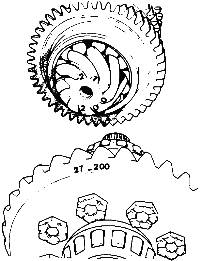
a) Crown wheel and pinion matching:
-
The final drive pinion and the crown wheel are lapped together during manufacture.
They therefore cannot be used separately.
Replacing one of these parts automatically involves replacing the other.
A common marking is inscribed on both the crown wheel and the pinion.
Example: 27-200.
UNDER NO CIRCUMSTANCES MUST ANY NOTICE BE TAKEN OF OTHER MARKINGS ON THE CROWN WHEEL.
b) Final drive pinion synchronizer hub matching.
-
The synchronizer hubs are matched with the final drive pinion.
- Checking the parts.
- If the final drive pinion, crown wheel or roller bearing are damaged.
-
Replace the crown wheel and pinion assembly. It is supplied with the bearing fitted to the final drive pinion tail shaft.
IMPORTANT
At present, the roller bearing is fitted with a circlip on the outer track ring and this has involved machining a groove in the gearbox housing.
The bearing, which is not fitted with a circlip, can be used in a housing that has a groove.
However, the bearing which has a circlip cannot be used in a housing which has no groove.
The synchronizers can be used again.
The size of the new final drive pinion to be ordered must be determined to ensure that the synchronizer hubs, which are to be used again, match the final drive pinion shaft.
To do this, measure the old final drive pinion.
-
If the synchronizers are damaged:
-
Replace the synchronizers.
The final drive pinion can be used again.
The size of the synchronizer hubs to be ordered must be determined in order to ensure that they match the final drive pinion. To do this, measure the final drive pinion.
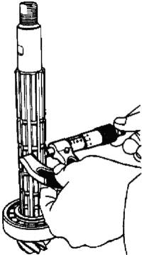
Measuring the final drive pinion
Measure the dimension across 2 of the splines on the final drive pinion shaft by means of a micrometer.
Take a number of measurements at different points around the splines at the point where the synchronizer hub fits and find the average.
Matching dimension chart.
-
There are 5 different size groups for the final drive pinion shaft, which correspond to 5 different synchronizer hub size groups.
They can be identified by a colour code paint mark.
- on the final drive pinion:
This mark can be found on the corresponding crown wheel along side the matching reference.
- on the synchronizers: it is to be found on the hub.
The synchronizer hubs are fitted to the final drive pinion shaft on the press:
-
- 1st - 2nd speed hub: hot, at a temperature of 250° C (482° F).
- 3rd - 4th speed hub: cold.
Once the size group has been determined, prepare the synchronizers as follows:
Final drive pinion Corresponding final drive dimension pinion and hub colour code ------------------------------------------------------------------ 16.55 to 16.57 mm White (.6516 to .6523") 16.58 to 16.60 mm (.6527 to .6535") Red 16.61 to 16.63 mm (.6539 to .6547") Blue 16.64 to 16.66 mm (.6551 to .6559") Yellow 16.67 to 16.69 mm (.6563 to .6571") Green |
- 1st - 2nd speed synchronizer:
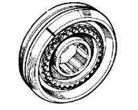
As the sliding gear wheel and the hub are matched, mark them before separating them:
- the position mark should be made on the 2nd speed gear wheel side, that is to say the same side as the chamfer, on the sliding gear wheel so that it can be seen after the hub has been fitted.
Place the hub in an electric oven and heat it to 250° C (482° F)).
Wait until it has reached full temperature before starting to re-assemble the secondary shaft assembly.
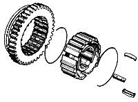
- 3rd - 4th speed synchronizer:
It is not necessary to dismantle this.
If it has been dismantled and can be used again, re-assemble it as follows:
Place the following on the hub.
-
- the three keys,
- the two springs (insert one end of each of the springs in one of the keys with the free ends on opposite sides of it).
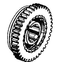
- the sliding gear wheel in the correct position, with the groove in the sliding gear wheel on the opposite side to the two notches in the hub, and the reference mark on the sliding gear wheel in line with the mark on the hub.(mark made during dismantling).
c) Re-assembling:
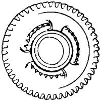
Place the synchronizer spring on the 1st speed gear wheel so that it covers the 3 notches.
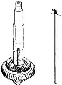
Place the following on the final drive pinion (already fitted with its bearing)
-
- the 1st speed gear wheel and its ring.
- the 1st speed gear wheel stop washer.
The dummy key is to be placed in one of the keyways, which has an oil hole in it.
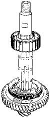
Take the 1st - 2nd speed gear wheel from the oven and place it on the final drive pinion in the correct position.
- the part with the position mark on it for positioning the sliding gear wheel is to face towards the 2nd speed gear wheel.
- one of the unsplined portion is to be in line with the dummy key.
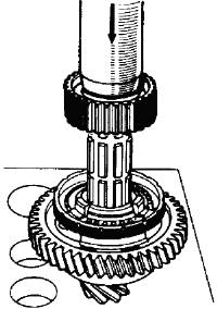
Push on the hub on the press until it makes contact with the stop washer. Hold the synchronizer ring in a central position, with the lugs below the level of the stop washer so as not to damage the spring.
Hold pressure on the press for a time in order to allow the hub to cool down. (Assist by cooling with compressed air).
Release pressure.
Remove the dummy key.
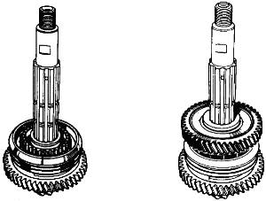
Fit the 1st - 2nd speed sliding gear wheel:
-
- with a chamfer on the 2nd speed gear wheel side.
- with the position reference in line with that on the hub.
Place the synchronizer spring on the 2nd speed gear wheel (in the same way as on the 1st speed gear wheel).
Position the 2nd speed gear wheel and its ring.
Position the gear wheel stop washer (turn it to align its splines with those on the final drive pinion shaft).
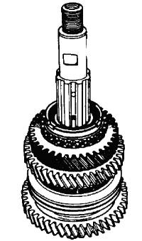
Fit the 3rd speed gear wheel and its ring.
Position the stop washer (turn it to align its splines with those on the final drive pinion shaft).
Fit the gear wheel stop washer retaining key (in one of the keyways that has an oil hole in it).
Fit the 3rd - 4th speed synchronizer on the press until it makes contact with the 3rd speed gear wheel stop washer:
-
- with the notches on the hub on the 3rd speed gear wheel side.
- one of the notches in line with the retaining key.
Warning: Ensure that the 3 notches on the synchronizer hub are in line with the 3 keys.
-
- the 4th speed gear wheel and its ring.
- the pinion depth adjusting washer (that was removed during dismantling).
- the double taper roller bearing and the speedometer drive worm gear.
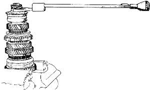
Grip the shaft in a vice, across the 1st speed gear wheel.
Engage 1st gear.
Tighten the speedometer drive worm gear by means of torque wrench (Part No 46E 6353) fitted with spanner (Part No 46F 6175):
10 to 12 m.da N (75 to 85 lb/ft).
2 - Differential
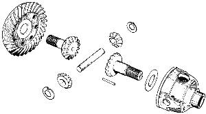
Fit the following in the housing:
-
- The bakelite impregnated washer (with the lubrication groove on the sun wheel side.
- The sun wheel (dipped in oil grade EP 80.)
- The planet wheels and their friction washers (the locating lug in the hole in the housing).
Dip the second sun wheel in oil grade EP 80 and fit it in the crown wheel.
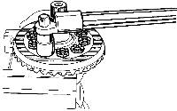
Fasten the crown wheel to the housing by means of new, self locking bolts (Part No 46F 6139).
Tighten the bolts to a torque of: 6 m.da N (45 lb/ft) using torque wrench (Part No 46E 6353) for the 10 mm (.394") diameter bolts.
3- Primary shaft
-
Whilst assembling the gearbox mechanism the following adjustments have to be carried out.
-
1 - Pinion depth
2 - Primary shaft bearing clearances.
3 - Differential bearings. (without play if original bearings) - (with given pre-load if new bearings).
The crown wheel/pinion backlash is adjusted after assembly.
1 - Adjusting the pinion depth
a) - Positioning the final drive pinion.
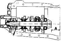
The final drive pinion is in its correct position when its front face is distance A from the crown wheel centre line. This position is obtained by placing a washer of a suitable thickness between the double taper roller bearing and the shoulder on the secondary shaft.
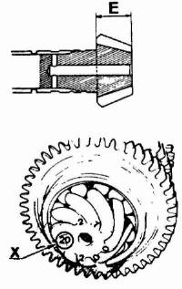
A = 53 mm (2.087").
- Flat front face on the final drive pinion:
- depth of pinion: E = 26.4 mm (l.040").
IMPORTANT:
All the 9 x 32 crown wheel and pinion sets supplied as spare parts must be at a pinion depth of: 53 mm (2.087").
Exceptional case.
It may be that under exceptional circumstances dimension A is not the pinion depth.
The difference (x) between the actual pinion depth at dimension A is then ma r ked on the front face of the final drive pinion alongside the matching reference.
It is given in hundredths of millimeters for example 20.
The pinion depth is then equal to A + the difference stated.
In the example given below it would be:
53 mm + 0.20 mm = 53.20 (2.087 + .008 = 2.095").
b) - Checking the pinion depth.
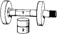
This operation is carried out with tool (part No 46F 6183), which comprises:
-
- a mandrel (1) which provides the crown wheel centre.
- a spacer (2) which is 42.5mm (1.673") high and which rests against the front face of the final drive pinion.
This spacer is used for adjusting the 53 mm (2.087") pinion depth.
Secure the left hand half-housing to support (Part No 46F 6176)
Fit the secondary shaft.
Fit the right hand half-housing and secure it in place by a number of bolts. (Do not tighten them).
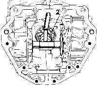
Temporarily fit the front housing to hold the double taper roller bearing track ring in position.
Tighten the half housing securing bolts.
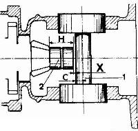
Fit mandrel (1).
Fit spacer (2) against the front face of the final drive pinion.
Measure, by means of a set of feeler gauges, the dimension X between the spacer and the mandrel.
-
- If the dimension measured is less than it should be, replace the final drive pinion depth adjusting washer by a thinner one.
- If the dimension measured is greater than it should be, replace the washer by a thicker one.
Washers are obtainable in thicknesses of 3.50 mm to 4.10 mm (.138 to .162") increasing in increments of 5/100 mm (.002").
When the final adjustment has been obtained, remove gauge (Part No 46F 6183), the front housing and the right hand half-housing.
Remove the secondary assembly and lock the speedometer drive worm
For the 53mm pinion depth:
The height (H) of spacer (2), which is 42.5 mm (1.673") plus the radius (C) of the shaft on plug mandrel (1), which is 10 mm (394") equals a dimension of: 42.5 mm+ 10 mm = 52.50 mm (1.673 + .394 = 2.067"). The dimension X to be measured between the spacer and the shaft on the mandrel is therefore: X = 53 mm - 52.5mm = 0.50 mm (2.087 - 2.067 = .020")
2. - Adjusting the differential bearings:
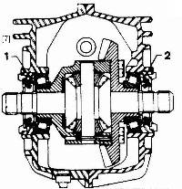
The adjustment is obtained by screwing nuts (1) and (2) in or out. [7]

Fit the corresponding bearing track ring to each half housing in such a way that it is slightly below the inner face of the housing.
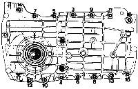
Fit the differential together with its bearings, into the left hand half housing.
Fit the right hand half housing and secure it by means of all its bolts.
Tighten the bolts with a torque wrench in the order shown:
-
- 7 mm (.276") diameter bolts: 2 m.da N (15 lb/ft).
- 8 mm (.315") diameter bolts: 2.8 m.da N (20 lb/ft).
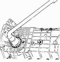
Smear the threads on the nuts and in the housing with 'Loctite AV' locking compound.
Screw the adjusting nut into each half-housing until it makes contact with the bearing track ring: Use wrench (Part No 46F 6179).
Two sets of circumstances may then arise:
-
If the original bearings are being used again
-
The differential must turn without play.
Continue to screw in the nuts, which push in the bearing track ring.
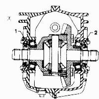
- Take care to screw in nut (1) on the differential housing side a little more than the one on the other side in order to obtain a crown wheel and pinion back lash which is slightly larger than that required on final assembly. [3]
When the differential can be felt to be turning without play, stop screwing in the nuts.
This is the final adjustment.
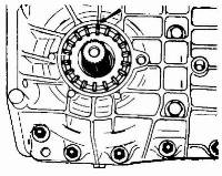
Mark the position of the nuts with reference to the housing (by means of a punch mark).
Remove the left hand housing and the differential.
When using new bearings.
-
New bearings must be fitted with a certain preload.
The differential should rotate with a resistance torque of between 0.050 and 0.150 m.da N. (.375 - 1.125 lb/ft).
Continue to screw in the nuts.
This pushes the track ring inwards:
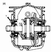
Take care to screw in nut (1) on the differential housing side by little more than the nut on the other side to obtain a backlash of a little more than the required figure on the final assembly. [4]
When the differential becomes slightly stiff to rotate, stop screwing in the nut.
Check the preload.
-
Checking the bearing preload.
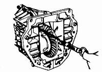
Turn the differential a number of times to centralize the bearings.
Wrap a string round the differential housing.
Pull on the string with a spring balance.
The differential should rotate under a load of between 1 and 3 da N (2 to 7 lb).
This is the load necessary to cause the differential to rotate.
If the adjustment is not correct, screw the nut on the differential housing side slightly in and check the preload again.
When the correct adjustment has been obtained mark the position of the nuts with reference to the housing.
Remove the left hand half housing and the differential.
3 - Adjusting the primary shaft bearings
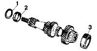
Place the following on the primary shaft:
-
- the bearing track rings (2) and (3)
- the adjusting washer (1) (removed during dismantling).
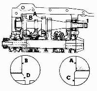
Fit the following into the right hand half housing:
-
- the primary shaft,
- the secondary shaft assembly.
This position is adjusted by means of washer (1):
Washers are obtainable in thicknesses of: 2.50- 2.75 -3- 3.25- 3.50 – 3.75 and 4 mm (.079 -.089- .108 -.118 - .128 - .138 - .148 - .158").
When the correct adjustment has been obtained, remove the secondary shaft assembly.
b) - Adjusting the bearings
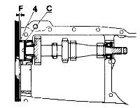
With the primary shaft in position, place the right half-housing in position without securing it.
Fit the adjusting shim (C) (removed during dismantling) and the spacer (4).
The shaft should turn freely, without play, and the spacer should project above the housing by 2/10 mm (.008") (the thickness of the paper gasket on the front housing.
Place a rule against the spacer and check the dimension (F) between the rule and the housing by means of a set of feeler gauges.
If the adjustment is not correct, increase or reduce the thickness of the shim pack C: shims are available in thicknesses of: 0.10 - 0.20 - 0.25- 0.50 and 1 mm (.004 - .008 - .020 - .040").
When the adjustment is complete, remove the right hand half housing and the primary shaft. Assemble the clutch to the primary shaft by securing the roll pin.
D - REASSEMBLING - Section Menu
1 - Gear shift control
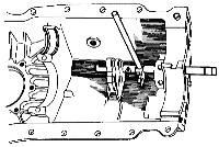
Engage the reverse shaft and the positioning fork (with its hub toward the differential end). Pin the positioning fork in place by means of drift (Part No 46F 6080).
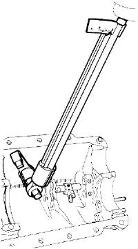
Fit the reverse swivel lever, engaging its end into its slot in the reverse shaft. Tighten its pivot to a torque of 2.8 m.da N (20 lb/ft) by means of torque wrench (part no 46E 6353).
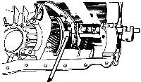
Fit the 1st - 2nd shift shaft locking ball and spring.
Insert the 1st - 2nd shift shaft.
Fit the 1st - 2nd shift fork (with the hub towards the control end) and pin it in place.
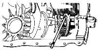
Fit the locking disc between the shafts.
Fit the 3rd - 4th shift shaft locking ball and spring.
Insert the shaft and fit the shift fork (with the hub towards the differential end) and pin it in place.
2 - Reverse shaft
-
Fit the following into the left-hand half housing:
-
- the locking ball and spring:
-
There are two springs of different lengths:
-
19 mm (¾") and 29 mm (1 5/32").
-
the 19 mm. (¾") spring is only to be fitted in housings which have no boss on the spring location.
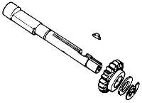
Engage the shaft and fit the gear wheel (with the hub towards the differential end) followed by the friction washer (with the bronze face towards the gear wheel).
Insert the guide from inside the bore and push the shaft fully in.
Fit the gear wheel retaining circlips.
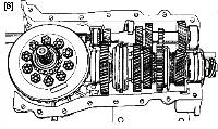
Fit the following to the right-hand half housing: [6]
-
- the primary shaft,
- the secondary shaft assembly.
Fit the differential to the left-hand half housing:
Fit the left-hand half housing to the right-hand assembly. Make sure that the end of the reverse swivel lever is in the slot of the reverse gear wheel shaft. Insert the half housing securing bolts but do not tighten them.
Fit the primary shaft bearing adjusting shims and the spacer.
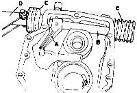
Fit the following to the rear housing:
-
- the internal shift lever A.
- the shaft B.
- the sealing rubbers C.
- the outside lever D.
- the slit in the pin must be square with the centre line of the shaft.
Fit a second pin inside the first:
- with the slit square with the slit in the first roll pin.
Bolt the outside lever to the shaft.
Screw in the breather.
Fit the speedometer drive wheel and its guide, fitted with an "O" ring seal.
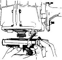
Fit the front housing paper gasket after first smearing it with a jointing compound. Position the rear housing, engaging the shift lever in the slot of the shift fork shafts.
Secure the housing in place without tightening down the bolts.
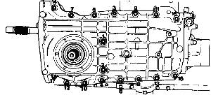
Tighten the half housing assembly bolts in the order shown on the illustration:
-
7 mm (.270") diameter bolts: 2 m.da N (15 lb/ft}.
8 mm (.315") diameter bolts: 2.8 m.da N (20 lb/ft).
E - ADJUSTING THE CROWN WHEEL AND PINION BACKLASH - Section Menu
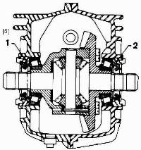
The back lash is obtained by screwing nut (1) on the differential housing side in or out and screwing nut (2) on the opposite side in or out by the same amount. [5]
Feel the backlash by hand.
If it is clearly too large unscrew nut (1) on the differential housing side and screw in nut (2) on the crown wheel side to obtain a smaller back lash before checking it with a dial indicator.
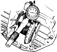
At this point, mount a dial indicator on the housing with its plunger square with the flank of one of the crown wheel teeth.
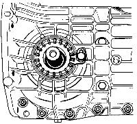
Check the backlash: It should be between 0.12 and 0.25 mm (.005 to .010").
If it is excessive, unscrew nut (1) on the differential housing side and screw in nut (2) on the crown wheel side by the same amount.
If there is insufficient backlash, unscrew nut (2) on the crown wheel side and screw in nut (1) on the differential housing side by the same amount.
When the correct backlash has been obtained, lock the nuts by means of the locking plates.
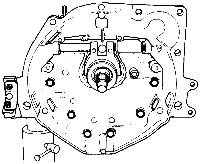
Smear the clutch housing paper gasket with a jointing compound.
Fit the clutch housing, paying attention not to damage the lip on the oil seal as it passes over the shaft splines. To do this wrap adhesive plastic round the splines. Tighten the housing securing bolts.
NOTE: The gearbox is to be filled with oil after it is refitted to the vehicle.
F.9 - REMOVING AND REFITTING THE REAR HOUSING - Section Menu
Removing.
-
Disconnect the battery.
Remove the luggage compartment.
Drain the gearbox, using spanner (Part No 46F 6187).
-
- the speedometer drive cable at the gearbox.
- remove the bolt which secures the reaction rod to the bracket on the gearbox.
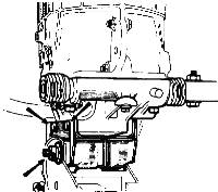
Unscrew the 2 nuts, which secure the rear mounting pad in order to free the two retaining washers.
Remove the 2 bolts, which secure the pad bracket to the rear housing.
Remove the pad and its bracket.
Lift the rear of the gearbox (transmission case) placing a spacer under it.
Remove the rear housing securing bolts and remove it.
Remove the gasket.
Clean the gasket face.
Refitting.
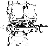
Fit the paper gasket smeared with a jointing compound.
Fit the housing, engaging the internal shift lever in the slot in the cross shaft.
Fit the housing securing bolts and tighten them.
Remove the chock from under the gearbox.
Secure the rear gear control shaft to the rose joint on the outside lever of the cross shaft.
Attach the speedometer drive cable. Connect up the reaction rod to the bracket on the gearbox.
Refit the luggage compartment.
Connect up the battery.
F.10 - GEAR CHANGE MECHANISM - Section Menu
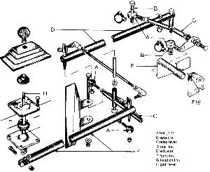
Two types of rear gear change linkage have been employed in the course of production of the LOTUS EUROPA.
-
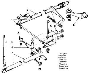
Series one vehicles utilised the linkage shown below, and in the exploded parts drawing opposite. On this model, the bellcrank situated between the front and rear gear control shafts, was pivoted from a bracket mounted on the timing case of the engine.
On series two cars this bellcrank bracket is chassis mounted. Other differences include the adoption of 'Rose' Joints where nylon swivels were previously used, a revised outside lever on the cross shaft, and a gear change reaction rod.
1) - Adjustment: Series one linkage.
A careful check should be made to ensure that there is at least 6 mm (¼") clearance between the ball joint 'A' and the timing case, when 1st and 3rd gears are engaged.
Packing washers may be inserted in conjunction with the spacers 'B' behind the bracket 'C'.
To ensure a smoothly operating gear change the use of a molybdenum disulphide lubricant is recommended on the pivots of the gear change lever.
A further check should be made on series one cars to ensure that there is adequate clearance between the battery box and the gear change shaft.
When reverse gear is engaged, there should be 6 mm (¼"') clearance between the battery box and the lever.
2) - Adjustment: Series Two linkage.
Early production series two vehicles were fitted with nylon insert ball joints.
Care should be exercised to ensure the correct fitting of the ball joint gaiters, as any ingress of moisture or grease can penetrate the nylon of the ball joints and cause premature seizure.
Linkages fitted with these joints (Part No. 46F 6161) should subsequently be modified, using the replacement metal type (rose Joint 5 46F 6151) at a convenient opportunity.
A careful check should be made to see if the ball joint of the reaction rod lies in a vertical position relative to the rear gear control shaft.
This is an essential for a smoothly operating gearchange and can be rectified in the following manner.
a - Detach the reaction rod from both the gearbox and the rear gear control shaft.
b - Extend the ball joint and lock it to the reaction rod with ¼" to 3/8" minimum thread engagement.
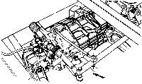
c - Add one, two, or three 5/16" flat washers between the other end of the rod and the rubber insulator grommet.
N.B: Use washer 5/16" x 5/8" x 16 SWG to bring the ball joint centre line into the required vertical condition.
ADDITIONAL INFORMATION
F.11 - GEARCHANGE LINKAGE ADJUSTMENT (Series 2 cars) - Section Menu
In addition to the information given on page 40 of this Section, the following information also applies.
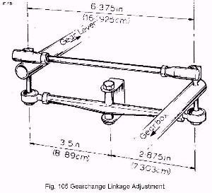
Commencing at Chassis No. 2340, new ball joints (Part No. A46 F 6161) were introduced to improve the smoothness of the gearchange linkage operation. To ensure a smooth gearchange it is essential that the ball joint/link assembly between the rear link and actuator (on gearbox), should be vertical when the gear lever is in "Neutral'; adjustment is controlled by the length of the location link (see illustration on Page 40).
-
1. Remove bolt from end of location link to release from gearbox mounting.
2. Ensure that location link is connected to the ball joint on the rear link with a .25 in. (6.35 mm.) to .375 in. (9.525 mm.) minimum thread engagement. If necessary, plain washers can be added to the other end of the link and rubber grommet to bring the link to the vertical position. The fixing bolt at this end must also have the same minimum thread engagement.
3. The ball joint on the rear link must be adjusted to give a dimension of 1.875 in (30.1625 mm.) from the face of the locknut to the outside edge of the ball joint.
4. The transverse links connecting the front and rear links are set on initial assembly and should not require adjustment. If however it is necessary to dismantle the transverse links for any reason, paragraph '5' and '6' below must be adhered to when re-assembling.
5. Ensure that the swivel faces of the relay lever bracket are free from dirt, underseal, etc. Liberally coat the swivel tube with grease before assembling the lever. Set the linkage to the dimensions given in Fig. 105.
6. Finally, ensure that the pivot bolt of the gear lever is slack enough to allow a friction free fore-and-aft movement while maintaining positive cross-gate movement.
F.12 - IMPROVED GEARSHIFT LINKAGE - Section Menu
An improved gearshift linkage has been introduced into current production, which gives a more positive and lightened operation. The linkage can be fitted to all Series II cars by proceeding as follows.
-
1. Raise the rear of the car and support with suitable stands. Support the engine/transmission unit with a separate stand.
2. Disconnect the clutch cable (see Section 'Q').
3. Remove the entire existing gearshift linkage, including the gear lever and the right-hand engine mounting bracket.
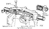
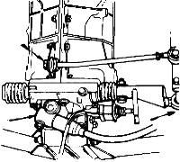
4. Remove the rear selector housing from back of gearbox (see Page 11 and 19). Remove the breather from the top of the housing. Pull off rubber boots from each end of cross-shaft and release circlip securing the return spring. Pull off spring abutment, spring and cup (Fig. 106).
5. Insert a suitable sized drift through the breather hole on top of the rear housing and knock out tension pins (inner and outer) securing selector fork to shaft. Slide cross shaft out towards the return spring side. Remove reverse spring and shorten to give a free length of 4.25 in. (107.95 mm) [8]. Re-assemble by reversing these instructions. Replace housing on gearbox.
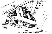
6. Drill a second hole of .25 in. (6.35 mm.) diameter on each 'leg' of the relay lever mounting bracket on the chassis. This second hole should have its centre .30 in. (7.62 mm.) from the centre of the existing hole (Fig. 107).
Extreme care must be exercised during this operation as the hole is quite close to the edge of the bracket.
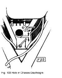
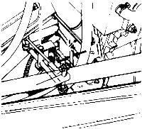
7. Enlarge the lower half of the hole in the chassis diaphragm by .25 in. (6.35 mm.) (Fig. 108).
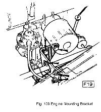
Fit new engine mounting bracket (Part No. B046 E 0378) and insert new rear longitudinal link (Part No. A065 F 0725) (Fig. 109).
8. Assemble actuator (Part No. A065 F 0163) to gearbox cross-shaft (on rear housing), using the 7 mm. roll pin (Part No. 046 F 6151) for its retention.
9. Insert front longitudinal link (Part No. A065 F 0158) into chassis backbone and attach gear lever (Part No. A065 F 0155). Attach bearing plate (Part No. A065 F 0169), spacer (Part No. A065 F 0156) and circlip (Part No. 046 F 6156) to chassis backbone and gear lever.
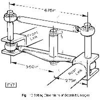
10. Attach relay lever (Part No. B054 F 0127) and link tube (Part No. A065 F 0160) to the rear longitudinal link. Attach relay lever to chassis bracket, using the newly drilled holes in the bracket. Attach front longitudinal link to the free ends of the relay lever and link tube. Adjust ball joints (Part No. 046 F 6161) on front and rear longitudinal links and on the link tube to give the dimensions shown in Fig. 110. Liberal greasing of the inner surfaces of pivot tubes (on ends of front and rear links) is desirable, BEFORE inserting the pivot bolts.
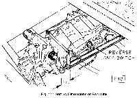
11. Attach the rear longitudinal link to the actuator and adjust ball joint to the dimension shown in Fig. 111. Attach location link (Part No. A065 F 0162) between rear longitudinal link and bracket on gearbox.
12. All locknuts should be torque loaded as follows:
-
5/16 in. nuts - 15 lbs. ft. (2.074 kg.m.)
3/8 in. nuts - 25 lbs. ft. (3.456 kg.m.)
Editors Notes:
-
[1] "Check" has been replaced by the word "Chock" (to prevent the car from rolling..). [SV]
[2] Added "Type 336/56". [SV]
[3] Changed numbers 1 and 2, which were transposed on the original drawing. [JJ]
[4] Moved the pointer and number 1 to the correct side of the drawing. [JJ]
[5] Changed numbers 1 and 2, which were transposed on the original drawing. [JJ]
[6] Replaced drawing to depict correct ring gear orientation. [JJ]
[7] Changed numbers 1 and 2, which were transposed on the original drawing. [JJ]
[8] Changed from 5.25 in. (107.95 mm) to agree with Lotus Service Bulletin 71/24 dated 23.4.1971. Likely a typo in the Service Manual since 5.25 in is not 107.95 mm. LOTUS reMARQUE article MAINTAINING SIDE-SHIFTING EUROPA GEARSHIFT LINKAGES – PART II - December 1984 suggests the length should be 3.75 in. [JJ]
Other Notes: [edit]
This area is a public scratchpad for notes.
Please be courteous with what you post, and do not erase someone else's work.


