- Hazard warning system.
- Brake fail warning system.
- Fasten seat belts warning system.
The main difference between the Europa Twin Cam model and the previous model is that of the alternator.
Wiring diagrams will be found at the end of this section. Printed copy only. Online wiring diagrams are available here. [JJ].
On cars destined for use in North America, the following are also incorporated into the electrical equipment specification:
M.2. - ALTERNATOR - Section Menu
- Do NOT polarize the alternator.
- Do NOT short across, or ground any of the terminals in the charging circuit, EXCEPT as given here.
- Ensure that both the alternator and battery have the SAME ground polarity.
- When connecting a charger to the battery, connect NEGATIVE to NEGATIVE and POSITIVE to POSITIVE.
- Undercharged battery, evidenced by a slow engine cranking and low specific gravity readings.
- Overcharged battery, evidenced by excessive water usage.
- Ensure that the undercharged condition has NOT been caused by accessories having been left on for excessive periods.
- Check the drive belt for correct tension.
- Inspect the wiring for defects. Check all connections for tightness and cleanliness including the slip connectors at the alternator and cable clamps and battery posts.
- With the ignition switch 'on' and all wiring harness leads connected, connect a voltometer from:
- Alternator '+' to ground.
- Alternator IND (NY) terminal to ground.
- Alternator BAT (NP) terminal to ground.
NOTE: The alternator is provided with a built-in safety feature which avoids overcharge and accessory damage by preventing the alternator from turning 'on' if there should be a break in the wiring harness connected to the BAT (NP) terminal.
Breaks in the wiring harness connected between the BAT (NP) terminal and the battery may be between the terminals, at the crimping of harness wire and terminal, or in the wire. - If paragraphs 1 through to 4 are satisfactory, now check the alternator as follows:
- Disconnect the battery ground (Negative) cable.
- Connect an ammeter in the circuit at the '+' terminal of alternator.
- Reconnect the battery (Negative) ground cable.
- Switch on windscreen wipers, lamps main beam, heater fan motor and radio if fitted.
Connect a carbon pile across the battery. - Operate engine at modest speed and adjust carbon pile to obtain maximum current output.
- If ampere output is within 10% of rated output (See TECHNICAL DATA), alternator is not defective; recheck paragraphs 1 to 4 inclusive.
- If ampere output is not within 100% of rated output, ground the field winding by inserting a screwdriver into the test hole (see fig. 2.)
CAUTION: Do NOT force screwdriver deeper than 25 mm.(1 in.) into end frame. - Operate engine at moderate speed and adjust carbon pile to obtain maximum current output.
Remove ammeter and switch off accessories.
- Check battery condition as normal workshop practice.
- Connect a voltometer from alternator BAT (NP) terminal to ground.
If reading is zero, BAT (NP) cable circuit is 'open'. - If battery and BAT (NP) cable circuit checks are satisfactory, but an obvious over-charge exists as evidenced by excessive water usage, then an internal fault exists in the alternator (i.e. field winding shorting, brush lead clip grounded or regulator defective), in which case, replace the alternator.
General Description.
-
The alternator features a solid state regulator which is mounted inside the slip ring end frame.
All regulator components are enclosed into a solid mould and this unit along with the brush holder assembly is attached to the slip ring frames.
The regulator voltage setting does NOT require adjusting and no provision is made for this.
The rotor bearings contain sufficient lubricant for the life of the machine.
Two brushes carry current through the two slip rings to the field coil mounted on the rotor and under normal conditions will provide long periods without attention.
The stator windings are assembled on the inside of a laminated core that forms part of the alternator frame.
A rectifier bridge connected to the stator windings contains six diodes and electrically changes the stator 'a.c.' voltages to a 'd.c.' voltage which appears at the alternator output terminals.
Field current is supplied through a diode trio which also is connected to the stator windings.
No periodic adjustments, or maintenance of any kind are required on the entire alternator assembly.
)
Fault Finding Procedure. (Fig. 1.)
-
Close adherence to the following procedure in the order given, will lead to the location and correction of charging system defects in the shortest possible time.
It will NEVER be necessary to perform all the procedures, in order to locate the trouble.
To avoid damage to the electrical equipment, ALWAYS observe the following precautions:
Trouble in the charging system will show up as one of the following:
Undercharged Battery.
-
This condition will be dealt with in the following manner:
)
Overcharged Battery.
)
Alternator Driving Belt Adjustment (Fig. 3.)
-
The belt is correctly tensioned when a total of 9.5 mm.(.375 in.) movement can be obtained on the belt mid-way between the pulleys at the top.
To adjust the Belt Tension.
)
- Between chassis and body - 8 inches long
- Between battery support bracket and body - 3 inches long
- Between body and battery base - 8 inches long
To ensure a positive battery clamping action, it is necessary to RETAIN the packing pieces fitted below the battery.
These are located at:
It is important to ensure also, that the nuts on the battery clamp rods are tightened sufficiently to ensure that the battery does not move on its base.
M.4. - HAZARD WARNING SYSTEM (where fitted) - Section Menu
The hazard warning system is operated by the horizontally mounted switch adjacent to the glove compartment.
When switched 'on', all four direction indicator lamps flash in unison, together with the warning lamp located in the centre of the facia panel.
Bulb failure in any of the direction indicator lamps will be shown by the warning lamp failing to flash, or flashing rapidly.
NOTE: Do NOT operate the direction indicator switch when the hazard warning system is in operation.
M.5. - BRAKE FAIL WARNING SYSTEM (where fitted) - Section Menu
M.6. - SEAT BELT WARNING SYSTEM (where fitted) - Section Menu
See Section 'B' Body.
M.7. - COOLING FAN MOTOR (where fitted) - Section Menu
Where moisture is found to be entering the cooling fan motor, it is recommended that Valvoline 'Tectyl 506' be brushed on to casing bolts, seams, etc.
Ensure that the sealant does NOT contaminate the motor terminals.
Drying time of the sealant is approximately 1 hour.
M.8. - PHILLIPS RN.314 'TURNLOCK' RADIO - Section Menu
- Filtering. A 1 mf. capacitor is fitted to each item
- Alternator casing to 'IND' cable (1 off).
- Voltage stabilizer 'BAT' terminal to earth (1 off).
- Wiper motor casing to 'fast speed' terminal and to 'slow speed' terminal (2off).
- Stop lamp switch terminal to terminal (1 off).
- Filtering. A 2 mf capacitor is fitted from the POSITIVE (+ve) side of the coil to an engine mounting block.
Keep clear of radius arm. - Bonding. Bonding braids are fitted as follows:
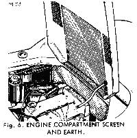
38 cm (15 in.) braid from bonnet hinge bolt to camshaft cover (see Fig. 6.)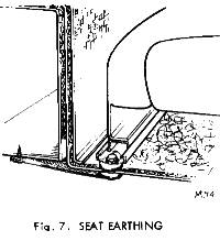
15 cm (6 in.) braid from each forward inner seat mounting bolt to chassis (see Fig. 7.)
30.5 cm (12 in.) braid from coil mounting bolt to chassis.
In addition to the above, check that the following connections have been made, these being incorporated in the main wiring harness (loom).-
Both fan motors to earth.
Wiper motor casing to earth.
R/H fuel tank to earth - this is most IMPORTANT. - Screening. Using Dunlop 'S.758' adhesive, attach a piece of perforated foil 53 cm.(22 in.) X 51 cm. (20 in.) to the underside of the engine compartment lid.
-
Note that the foil is beneath the bonnet mounting nuts with the braid in contact with the foil (see Fig. 6.).
Full details for fitting a radio are given in Section 'M' of the Europa Workshop Manual.
The Phillips radio receiver is earthed to a convenient body-to-chassis mounting bolt.
Feed to the receiver is from the 'AUX' side of the ignition/starter switch, through an in-line 2 amp fuse.
)
The aerial is fitted to the passenger side of the car (see Fig. 5.) with the co-axial lead running behind the top of the carpet in the foot well.
The single speaker is fitted behind the door trim panel in the passenger door.
Suppression required with this radio to give a reduction of interference to an acceptable standard, proceed as follows:
)
)
M.9. - SWITCHES - Section Menu
North American cars are fitted with new switches from Chassis No. 72082684R onwards. These are:
)
Windscreen Wiper/Washer Control
-
Move the lever downwards to the FIRST position (A).
The wiper speed is increased by moving the lever further downwards to the SECOND position (B).
To 'flick wipe' the screen, move the lever UP (C) and hold for duration of wipe.
On release, the lever will automatically cancel and return to the 'off' position, the blades returning to their normal position.
To use the screen washer, push in the lever towards the steering column (D), and release.
To remove the switch
-
Remove the steering wheel
Release the switch clamp on the steering column.
Pull out cable multi-plugs at lower end of column, and remove switch.
Note that the switch is an assembly together with the headlamp/horn switch.
)
Horn, Direction Indicators and Headlamp Switch.
Horn:
-
Push the lever in towards the steering column, and release (A).
Direction Indicators:
-
Move lever FULLY up for right-hand turn (B) and FULLY down for left-hand turn (C).
Switch will cancel when steering wheel is moved to execute turn.
For 'lane changing', move lever up (D) to FIRST position and hold for right-hand change, and down (E) to FIRST position, holding for left-hand change.
Headlamps:
-
Main beam is obtained with the lever in the downwards position (F); to select dipped beams move the lever upwards (G).
These positions are only operative when the lighting switch (Fig.10) is in operation.
Lifting the lever towards the steering wheel (H) flashes the headlamps main beams irrespective of the position of the lighting switch.
To remove the Horn, Direction Indicators and Headlamp Switch, see under the heading 'Windscreen Wiper/Washer Control'. The two switches are mounted on a common base plate, thus forming an assembly.
)
-
Turn knob fully to the right, in direction of arrows (Fig.10), to switch 'on' the side, rear and tail lamps; pull the knob fully out while in the turned position, to energize the headlamps.
To remove the switch
-
Depress the knob locking peg and pull off knob.
Turn the slotted nut in an anti-clockwise (counter-clockwise) direction, remove nut and, from front of facia, push switch out.
Mark position of cables, then release.
)
Panel Lamps Switch.
-
Turn the knob to the right in the direction of arrow (Fig. 11), to illuminate the panel lamps.
The switch incorporates a rheostat which, when the knob is turned further to the right, reduces the glow from the lamps.
The switch is only operative when the lighting switch is in operation.
To remove the switch
-
Depress the knob locking peg and pull off knob.
Turn the slotted nut in an anti-clockwise (counter-clockwise) direction, remove nut and, from front of facia, push switch out.
Mark position of cables, then release.
)
)
M.10. - CONTROL ILLUMINATION - Section Menu
Commencing at Chassis No. 72082684R, all cars destined for use in North America are fitted with control illumination (see Figs. 12 and 13).
To replace any of the illumination bulbs, simply pull from their location, fit new bulbs, and replace holders.
Online wiring diagrams are available here. [JJ].
Other Notes: [edit]
This area is a public scratchpad for notes.
Please be courteous with what you post, and do not erase someone else's work.