Amp gauge
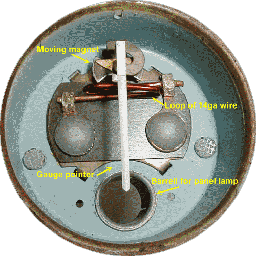
The Lucas amp gauge is a simple device and its internals are pictured below.
Operation
Electrical current from the battery passes through the amp gauge to get to all electrical devices in the car. The path through the gauge is a loop of 14ga solid copper wire. The pointer is designed so that it rests in a centered position. All that is needed to make the meter deflect is current flow through the coil. At the pivot point of the pointer is a magnet structure. Remember that DC current in a coil creates a magnetic field. When current flows one way through the coil (charge), a magnetic field aligned one way will be created. If the current is reversed (discharge), the magnetic field will align the opposite way. The polarization of this magnet (North/South) is such that the magnet will be pulled one way or the other depending on the direction of current flow through the loop. The accuracy of this gauge is dependant on the strength of the pointer magnet, the physical characteristics of the loop and the pointer bearing friction. I wouldn't expect great accuracy from such a gauge but it does work. Unlike the other Lotus electrical gauges, the amp gauge is a fast acting one.
The following picture shows the layout of the internal components of the amp gauge. Click on the picture to see actual pointer motion.

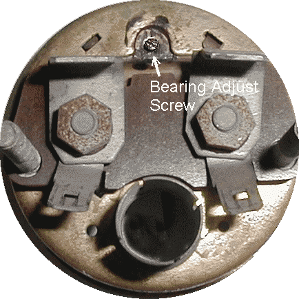
The following picture shows the back side of the amp gauge. Unlike the other
gauges, there is no calibration adjuster. There is a screw that is used to
adjust the bearing. Using a suitable size flat blade screwdriver, you adjust the
bearing so that the pointer neither drags or is too loose. Turning the screw
clockwise tightens the bearing. Be careful not to over tighten it or it may get
damaged. If you make this adjustment, secure the screw with something like
finger nail polish. Just pick a really nice color. 
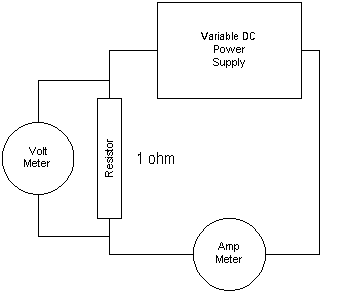
I decided to check the accuracy of this meter. To do this, I used a large variable DC power supply, a 1 ohm 100 watt resistor and a voltmeter. Because current is equal to voltage divided by resistance (I=E/R), every volt measured on the voltmeter equals an amp of current in the circuit. I connected the parts as follows:
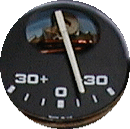
The pictures below show that the meter was reading a little high. I had 10 volts across the resistor so it should have indicated 10 amps. It was actually showing about 13-14 amps.
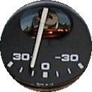
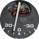
I just hate inaccuracy so I adjusted the accuracy by slightly bending the coil away from the moving magnet. I reasoned that the meter was reading too high because it was a bit to sensitive. Moving the coil away from the magnet would reduce the sensitivity. You have to experiment here. I would estimate that I moved the coil about .050" (1.27mm). If you try this, be careful to not damage the pointer assembly. You can see the results in the following pictures:

Last update: 22 Nov. 2003