Source: Lotus West
Author: Tom Dill
Date:
Title: UNDERSTANDING THE WEBER CARBURETOR
LW# 00FU038 Also includes 00FU041 and 00FU042
One of the better parts on earlier twincams is the Weber. Since many are mystified by them and their awesome look, they are afraid to even look crosseyed much less work on them. The following series of articles lays bare the function and parts designation of the carburetor. Most of the series has been lifted from A Guide To Tuning, Warnerford, Warnerford, Australia. Float leveling has been skipped as most manuals deal well with this.
IDLE JET
Both the DCOE and IDA carburetors have an idle jet assembly, which meters both fuel and air into the idle circuit.
At idling speed the idle mixture adjustment can be set to control the volume of mixed or emulsified fuel and air provided by the idle jet assembly and if a correct jet has been selected the setting of the idle mixture screw should be between a quarter and one full turn open.
As the throttle is opened from the idling position the throttle disc crosses a series of holes, which are referred to as the secondary idle bleed circuit or transfer holes. These are fixed holes having no adjustment and are also fed by the idling jet assembly. Naturally it is important that a controlled mixture is fed through them so that smooth acceleration takes place from idle until the main jet assembly comes into operation. The control of this mixture is very closely associated with the idle jet air bleed (the ‘F’ number in DOCE units…).
SELECTION
To determine these jet hole sizes tables have been prepared. Table 2 deals with the fuel bleed hole designated by the number 35, 40, 45, 50, 55, etc, and the sizes are given in mm. against the capacity of each cylinder. Where an engine has Siamese inlet ports it may be necessary to go one size larger than quoted.
TABLE NO.2

Cylinder Size in cc	Idle Jet Fuel Bleed Hole Size mm
200				.35 to .40
250				.40 to .45
300-350				.45 to .50
400				.50
450-550				.50 to .55
600				.55 to .60
650				.60 to .65
700				.65 to .70
750-850				.70 to .75
Table number 3 gives the size of the idle jet air correction or bleed hole or holes against each ‘F’ number in mm’s. It will be seen that ‘F’ numbers do not run in sequence, but in table number 4 they have been arranged in their order from rich to lean.
Table No.3

		One Hole Type		Two Hole Type
‘F’ Number	Hole Sized in mm.	Hole Sized in mm.

F1						1.35
F2			1.30
F3						1.60
F4			1.35
F5			1.60
F6			0.65
F7						1.20
F8			1.20
F9			1.00
F10 No hole, for use in IDA carburetor where air correction is in idle jet carrier or holder.
F11			1.25
F12			0.85
F13						0.90

Table No.4

Idle jet air correction or bleed holes arranged from rich to lean.
Rich - F6 F12 F9 F8 F11 F13 F2 F4 F5 F7 Fl F3 - Lean
Example
Take a four- cylinder engine of 1275 cc., divide by 4, this is 319 cc per cylinder. From table number 2 it shows that both 300 and 250 cc's can use as a starting point either a 45 or 50 idle fuel bleed hole size but as the example has Siamese ports, the 50 is the jet to start with.
To get a reading for the correct selection of the idle air bleed or ‘F’ number hole size it is recommended that a midway choice be made F8 (1. 20mm) be used which will give an idle jet assembly number of 50F8.
To check this selection start the engine and bring it up to the normal operating temperature; leaving chokes, secondary venturies, mains, emulsions, air corrections, etc, as fitted. Carefully set the idle mixture screws (see diagrams numbers l and 2) taking time to allow engine to settle down after each adjustment (this is done in conjunction with the idle speed screw, see diagrams l and 2) and when set to the most even idling position - due allowance made if a competition camshaft is being used as this will produce rough idling generally.
After completing this operation, open the throttle and hold it steady at 200 - 2500 rpm - below where the main jet would enter the circuit and check with a gas analyzer which should read 12.5 to 13.1 air fuel ratio. If an analyzer is not available, a quick means of determining the mixture is by listening to the engine, if it is backfiring through the carburetors, the mixture is too lean and conversely too rich if backfiring through the exhaust. If it is found necessary to change the idle jet selected; reference to the ‘F’ number scale, tables 3 and 4 shall indicate the appropriate change. When a change has been made carry out the aforementioned procedure again.
CHOKE TUBE
The choke tube governs the gas speed through the carburetor. As the choke tube and carburetor size is very closely associated the following information can be used as a guide to carburetor size selection as well if this has not already been done.
The main points to be kept in mind when selecting choke tubes sizes are as follows:(1)
(1) Use of the vehicle - road or track, if track
a) Hill climbing, good torque characteristics required, smaller chokes.
b) Road racing, fast circuits which require more power at the top end of the rev range, larger chokes. Slow circuits, which require better torque, smaller chokes.
(2) Weight of the vehicles, the lighter the vehicle for a set eng capacity, increase the choke size.
A Guide to Choke Tube Selection
4 cylinder engine, with an inlet port per cylinder. (Push rod valve operated engines in production touring or sports cars e.g. Volvo, Morgan).
			STATE OF TUNE OF ENGINE

Capacity Per		Standard	High:Perfor-	Competition
Cylinder in cc's	Choke size in	mance. Choke	Choke Size	Carburetors
			mm		size in mm	in mm
200							27		38 DCOE x2
250			27		28		30		38 DCOE x2
			27		28		30		40 DCOE x2
300			27		29		31		40 DCOE x2
350			29		31		33		40 DCOE x2
400			30		33		36		40 DCOE x2
			30		32		35		42 DCOE x2
450			32		34		36		40 DCOE x2
Secondary or Auxiliary Venturi
Secondary venturies are supplied in the following sizes 3.0, 3.5, 4.0, 4.5, 5.0 depending on the various model DCOE and IDA carburetors. These sizes relate to the cross feed hole which delivers fuel from the main jet assembly. The feed hole is rectangular in shape having a radiused edge at feed end and tapered slightly towards the delivery point in the venturi proper.
Small secondary venturies (3.5) should be used where a large choke tube has been selected in relation to the cylinder capacity.
Main jet, Emulsion Tube, Air correction jet Assembly.
This assembly screws into a fuel well having three delivery points.
1) Bottom - inlet hole through which the main jet draws fuel from the float chamber.
2) Top - Air inlet through which the air correction jet supplies air the emulsion tube.
3) Side - mixed or emulsified fuel and air outlet to the secondary or auxiliary venturi.
Function
When the air flow through the secondary venturi is of sufficient velocity fuel is drawn from the annular space in the emulsion tube well. This space can be varied by the use of emulsion tubes having the same number, size and disposition of holes, but of different diameter e.g. F2 and F15; F3 and F7. Therefore to obtain a large initial flow of fuel a small diameter emulsion tube should be used. As the fuel level drops in the well, the main jet replaces it up towards its normal level subject to the volume of fuel being drawn from the emulsion tube well by the second venturi. The rate of fuel drawn from the emulsion tube well is governed by the air speed through the secondary venturi and this speed varies according to the engine demands, consequently as the fuel level drops, it uncovers the correction holes in the emulsion tube, resulting in a corrected mixture. So it will be seen that a number of factors control the delivery of fuel to the engine.
1) Size of the secondary Venturi.
2) Diameter of the emulsion tube.
3) Size of the main jet.
4) Size of the air correction jet.
5) Number and disposition of air bleed holes in the emulsion tube.
Dealing with above items 1 and 2 have already been discussed, Item 3 the main jet, usually can be calculated, as a good starting point by multiplying the choke tube size by 4 e.g. 30 choke tube multiplied by 4 equals a 120 main jet.
Item 4, the air correction jet size, does not have a simple formula as the main jet. It can be classified in three basic groups.
a) Standard and high performance- engines using DCOE carburetors, (but not Siamese ported 4 cylinder engines) the air correction jet size is usually the main jet size plus 60 e.g. 120 main gives a 180 air correction jet.
b) DCOE carburetors used on racing engines, the air correction can be as suggested in a) or the same size as the main jet (this is usually the case when large choke tubes are used in relation to cylinder capacity and carburetor size) e.g. 2.5 litre 4 cyl inder Coventry Climax engine 58 DCO 3 carburetors 47mm chokes 200 main jets and 200 air correction jets.
c) IDA carburetors only on competition vehicles, the air correction jet is usually the main jet size minus 50 to 60. A 170 main uses a 110 to 120 air correction jet.
Accelerator Pump - Power Circuit
The pump circuit is made up by several parts, listed below are the items in order of their operation.
1) Intake valve.
2) Pump well.
3) Pump rod, spring and piston assembly.
4) Exhaust orifice.
5) Pump jet.
6) High speed power device.
1) Intake valve, this is found in the bottom of the float chamber between the “jet block” and the pump well. The valve incorporates the exhaust orifice 4) which shall be explained later. The intake valve is a fixed size and therefore is not necessary to consider when tuning is being carried out; its function is to allow fuel to pass into the pump well.
2) Pump well is a fixed size store for the pump jet, but is metered by two units, the pump rod and the exhaust orifice.
3) Pump rod, spring and piston assembly, the pump rod governs the amount of fuel in the pump well. The OCOE model carburetor has varying lengths of rods available to change this volume factor while the IDA unit can be changed by the use of a collar on the pump rod to shorten its stroke. Piston spring, the speed of thrust of the pump piston can be altered by the use of springs of different pressures.
4) Exhaust orifice the feature of this unit is to control the amount of fuel at the disposal of the pump jet. Consequently there are varying sizes of this unit starting with the “closed” or type with no exhaust orifice which gives the pump jet all the fuel available in the pump well to the pump Jet, whereas the others exhaust an amount in accord with their size back into the float chamber.
5) Pump jet, this does exactly as the name suggests, and that is to meter the amount of fuel available from the pump well or govern the volume and time of flow of fuel.
6) High speed power device, in the DCOE and IDA carburetors the pump jet also acts as a high speed power device. When the depression in the carburetor bodies or throat. becomes great enough, the ball and rod weight is lifted off its seat in the DCOE and a ball check valve in the IDA and fuel bleeds into the system via the pump jets.
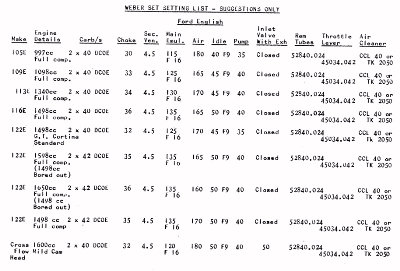
For assistance in the selection of the pump circuit parts, refer to the table listing Weber Set Setting list.